
Applying Signal Reference Rules
To change EMI Scanner Signal Reference rules:
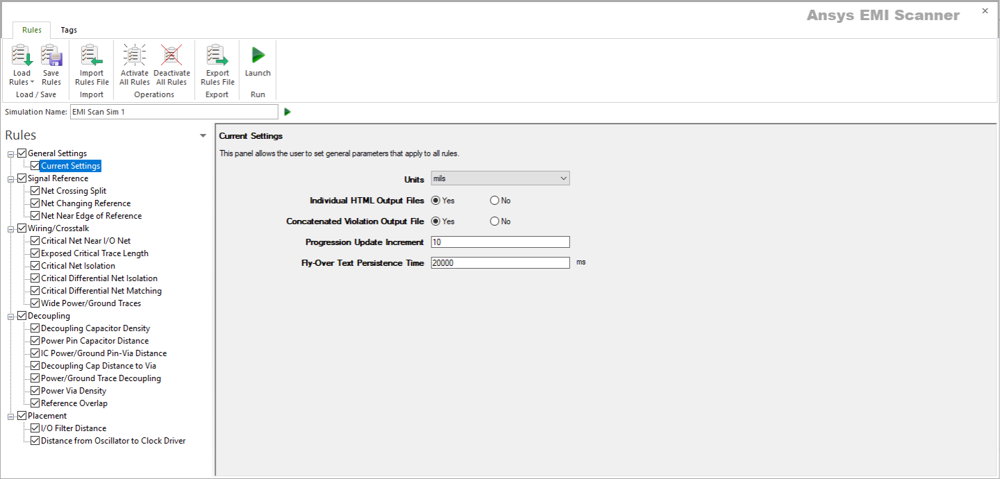
- Launch EMI Scanner.
The EMI Scanner window appears, on the Rules tab.
- From the Rules pane, select one of the three subcategories under Signal Reference:
- Net Crossing Split – displays Critical Net Crossing Split Reference Plane rule configuration.

This rule states that critical nets must not cross a split in the adjacent reference plane. A cross is allowed only if two stitching capacitors are within a specified distance of the crossing.
From here, you can set the following:
- Rule State – toggles Net Crossing Split rules on or off.
- Max Allowable Distance from Net Crossing to Stitching Caps – sets the maximum distance from the point where the net crosses a split in its reference plane. Two stitching capacitors must be found within this distance.
- Max Allowable Return Current Diversion – sets the maximum distance for a return current diversion. If a signal's return current can divert itself around the gap in the reference plane, the total distance of the diversion must be less than this value.
- Sort by Column – specifies the column by which results are sorted.
- Log File State – determines whether EMI Scanner creates a log file with additional details (intended for use in debugging).
- Weighting Factor – specifies the weighting factor (0<factor<=1) that is applied to violations of this rule when assigning a rank. A violation's rank is its own "degree of badness" multiplied by the weighting factor. See Exporting EMI Scanner Results and Analyzing EMI Scanner Results Using iQ-Harmony.
- Only Identify Gaps Between Planes on Same Layer – determines whether gaps are only between planes on the same layer or not. When the rule tries to pair up nearby plane boundary crossing points and identify gaps, this parameter enables or disables a check for layer commonality.
- Recognize Dual Plane Reference Within – instructs EMI Scanner to consider both planes as a reference when checking for gap crossing when the distance difference to each plane is less than the specified distance. This allows recognition of both planes as references for strip line traces when the trace is offset from the exact center by a small amount (normally for manufacturing reasons).
- Max Distance Between Crossing Points for Combination as a Single Gap – sets the maximum distance for combining crossing points into a single violation (e.g., the entrance and exit of a gap between planes). Too large a value can cause the algorithm to pair up unrelated crossing points, and too small a value can prevent crossing points from being paired up, resulting in more violations. It is recommended to set the value to a reasonable distance based on the board design technology being used (e.g., slightly larger than the typical plane separation within a layer).
- Suppress Violation for Traces Connected to Via in Gap – determines whether to ignore trace crossing split/gap when connected to a via within that gap.
- Max Distance from Reference Plane for Via in Gap – sets the maximum distance for which via violations within a gap will be suppressed. If the trace extends greater than this distance from the edge of the reference plane to the via, its violation will not be suppressed.
- Net Choice – specifies the nets to include in this rule analysis. Select one, or Ctrl+click to select multiple nets.
- Net Changing Reference – displays Critical Net Changing Reference Plane rule configuration.

This rule states that critical nets must not change reference planes.
Note:- Any change in the reference plane for a critical net will cause a violation.
- Reference plane changing is allowed if two decoupling capacitors (or vias if the planes share the same net name) are within a specified radial distance from the signal via where the signal changes reference planes.
- Reference plane changing is allowed if three decoupling capacitors (or vias if the planes share the same net name) are within a specified radial distance from the signal via where the signal changes reference planes.
- Reference plane changing can be ignored when the initial via is within a specified distance from its IC pin (transmit or receive).
From here, you can set the following:
- Rule State – toggles Net Changing Reference rules on or off.
- Sort Changing Reference Violation by Column – specifies the column by which Changing Reference Violation results are sorted.
- Sort Capacitor/Via Violation by Column – specifies the column by which Capacitor/Via Violation results are sorted.
- Sort Overused Via Violation by Column – specifies the column by which Overused Via Violation results are sorted.
- Log File State – determines whether EMI Scanner creates a log file with additional details (intended for use in debugging).
- Overused Return Vias – determines whether EMI Scanner checks for overused return vias.
- Max Current Limit – specifies the maximum number of signal currents that a via should carry. Use in conjunction with Overused Return Vias.
- Weighting Factor – specifies the weighting factor (0<factor<=1) that is applied to violations of this rule when assigning a rank. A violation's rank is its own "degree of badness" multiplied by the weighting factor. See Exporting EMI Scanner Results and Analyzing EMI Scanner Results Using iQ-Harmony.
- Recognize Dual Plane Reference Within – instructs EMI Scanner to consider both planes as a reference when checking for gap crossing when the distance difference to each plane is less than the specified distance. This allows recognition of both planes as references for strip line traces when the trace is offset from the exact center by a small amount (normally for manufacturing reasons).
- Allow Partial Reference Plane Change – instructs EMI Scanner to ignore a violation if one of the two reference planes remains a reference plane on both sides of the via transition.
- Check for Plane Decoupling – instructs EMI Scanner to ignore a violation if a decoupling capacitor exists between the two reference planes (entering reference plane and leaving reference plane) and is within a specified distance of the signal via (see additional settings below).
- Include ALL Reference Plane Changes – instructs EMI Scanner whether to display all reference plane changes. When there are two associated reference planes for the entry to the via, and two different associated reference planes for the trace leaving the via, selecting 'yes' will show two violations for this transition. If 'no' is selected and a decoupling capacitor exists between one of the entering reference planes and one of the leaving reference planes (within the specified distance), no violation will be reported, even though the two other reference planes do not have any connection.
- Number of Vias Allowed on Net – specifies the number of via reference plane changes that are allowed on critical nets. If no vias are appropriate except the 'escape' via close to the IC, set this parameter to zero, and set Allow Via Close to IC to 'yes'.
- Allow Via Close to IC – determines whether to ignore vias that are close to the IC and are required to get a trace from the surface to an inner layer.
- Max Distance from IC to Ignored Via – specifies the maximum distance between IC and via at which vias are ignored.
- Use Point-to-Point Distance from IC to Via – if 'yes' is selected, the actual trace path length is NOT calculated. This option allows EMI Scanner to check rules faster, but may cause violations to be ignored incorrectly.
- Allow Via Connection Between Reference Planes – allows a via to be used to connect reference planes (to provide return current path) when the two reference planes share the same net name.
- Allow Complex Via Connections (Jogging) Between Planes – allows a set of vias (e.g., 'blind' vias that do not extend through all layers) to be used to connect reference planes (to provide return current path) when the two reference planes share a net name. This advanced checking requires extra processing time because all vias found in the larger via radius are considered as potential paths.
- Num of Decoupling Caps Required Within Smaller Radius – when Allow Partial Reference Plane Change is selected, a return current path (when a critical net changes reference planes) may be provided with either capacitors or vias. This setting specifies the number of capacitors required within the smaller radius.
- Num of Vias Required Within Smaller Radius – when Allow Partial Reference Plane Change is selected, a return current path (when a critical net changes reference planes) may be provided with either capacitors or vias. This setting specifies the number of vias required within the smaller radius. A via between planes is a lower impedance/inductance connection then a decoupling capacitor, so you may want to specify a different setting.
- Small Radius Allowable Capacitor Distance – specifies the smaller radius used with the Num of Decoupling Caps Required Within Smaller Radius setting.
- Small Radius Allowable Via Distance – specifies the smaller radius used with the Num of Vias Required Within Smaller Radius setting.
- Num of Decoupling Caps Required Within Larger Radius – if a smaller radius is not specified, this allows specification of a larger radius for a larger number of decoupling capacitors.
- Num of Vias Required Within Larger Radius – if a smaller radius is not specified, this allows specification of a larger radius for a larger number of vias. A via between planes is a lower impedance/inductance connection then a decoupling capacitor, so you may want to specify a different setting.
- Large Radius Allowable Capacitor Distance – specifies the larger radius used with the Num of Decoupling Caps Required Within Larger Radius setting.
- Large Radius Allowable Via Distance – specifies the larger radius used with the Num of Vias Required Within Larger Radius setting.
- Additional Search Range Percent – specifies an additional search range beyond the larger radius for additional capacitors. For example, if the larger radius is set to 500mils and the Additional Search Range Percent is 100%, EMI Scanner will report capacitors within 1000mils when a violation occurs.
- Force All Plane Combinations to Be Decoupled – determines whether to decouple all reference plane combinations. See Technical Note.
- Net Choice – specifies the nets to include in this rule analysis. Select one, or Ctrl+click to select multiple nets.
- Net Near Edge of Reference – displays Critical Net Near Edge of Reference Plane rule configuration.

This rule states that critical nets must not be within a specified distance of the edge of their reference plane.
From here, you can set the following:
- Rule State – toggles Net Near Edge of Reference rules on or off.
- Min Distance from Edge Required for External Signal Layers – specifies the minimum distance that must exist between the edge of the reference plane and a critical signal net when the net is on an external layer.
- Min Distance from Edge Required for Internal Signal Layers – specifies the minimum distance that must exist between the edge of the reference plane and a critical signal net when the net is on an internal layer.
- Sort by Column – specifies the column by which results are sorted.
- Log File State – determines whether EMI Scanner creates a log file with additional details (intended for use in debugging).
- Weighting Factor – specifies the weighting factor (0<factor<=1) that is applied to violations of this rule when assigning a rank. A violation's rank is its own "degree of badness" multiplied by the weighting factor. See Exporting EMI Scanner Results and Analyzing EMI Scanner Results Using iQ-Harmony.
- Use Edge of Board (Instead of Edge of Plane) – allows you to check distance from critical nets to the edge of the board instead of the edge of the reference plane. This can be useful if the board is only partially complete and all reference planes are not yet completed.
- Check All Plane Edges – checks the distance from nets to any edge of their reference plane, rather than limiting the check to reference plane edges near the edge of the board
- Ignore Violation If Net Approaches Edge at 90 Degrees +/- – EMI Scanner ignores edge connectors that approach the edge of the reference plane or board at a 90 degree angle. This option specifies a tolerance that allows the approach to be slightly off a perfect 90 degrees.
- Check Nets on External Layers – specifies whether nets on external layers should be checked.
- Check Nets on Internal Layers – specifies whether nets on internal layers should be checked.
- Minimum Net Segment Length for Violation – specifies the minimum net segment length before EMI Scanner will report a violation if the net is within the specified distance from the edge of the reference plane or board.
- Recognize Dual Plane Reference Within – instructs EMI Scanner to consider both planes as a reference when checking for traces too close to the edge of the reference planes when the distance difference to each plane is less than the specified distance. This allows recognition of both planes as references for strip line traces when the trace is offset from the exact center by a small amount (normally for manufacturing reasons).
- Net Choice – specifies the nets to include in this rule analysis. Select one, or Ctrl+click to select multiple nets.
- Net Crossing Split – displays Critical Net Crossing Split Reference Plane rule configuration.
- Rules are automatically saved for the current EMI scan. To save them for a future scan, click Save Rules.
Note:
- You can display a description of a rule parameter at any time by hovering the cursor over it.
- Units of measure are set in General Settings.