
Applying Net Integrity Rules
To change EMI Scanner Net Integrity rules:
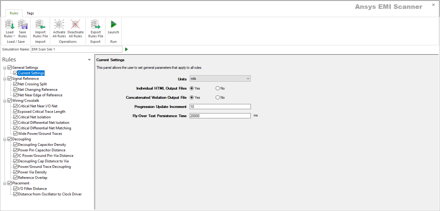
- Launch EMI Scanner.
The EMI Scanner window appears, on the Rules tab.
- Click Load Rules and select a profile containing Signal Integrity rules (e.g., Default SI Rules Profile).
- From the Rules pane, select one of the eight subcategories under Net Integrity:
- Net Length – displays the Net Length rule configuration.

This rule states that a critical net's length between pins of ICs and Connectors must not be more than a specified value.
From here, you can set the following:
- Rule State – toggles Net Length rules on or off.
- Maximum Net Length – specifies the maximum net length.
- Sort by Column – specifies the column by which results are sorted.
- Log File State – determines whether EMI Scanner creates a log file with additional details (intended for use in debugging).
- Weighting Factor – specifies the weighting factor (0<factor<=1) that is applied to violations of this rule when assigning a rank. A violation's rank is its own "degree of badness" multiplied by the weighting factor. See Exporting EMI Scanner Results and Analyzing EMI Scanner Results Using iQ-Harmony.
- Net Choice – specifies the nets to include in this rule analysis. Select one, or Ctrl+click to select multiple nets.
- Net to Net Coupling – displays the Net Coupling rule configuration.

This rule states that critical nets and other signal nets may not be closer than a specified minimum distance.
From here, you can set the following:
- Rule State – toggles Net Coupling rules on or off.
- Minimum Separation Between the Nets – controls how close the nets can be before they are considered coupled.
- Maximum Coupling Length – specifies how much coupling must exist before a violation is reported.
- Sort by Column – specifies the column by which results are sorted.
- Log File State – determines whether EMI Scanner creates a log file with additional details (intended for use in debugging).
- Weighting Factor – specifies the weighting factor (0<factor<=1) that is applied to violations of this rule when assigning a rank. A violation's rank is its own "degree of badness" multiplied by the weighting factor. See Exporting EMI Scanner Results and Analyzing EMI Scanner Results Using iQ-Harmony.
- Minimum Segment Length – specifies the smallest net segment length to check for coupling. Any segments smaller than this length will be ignored.
- Layer Threshold – sets the number of layers above and below to check for coupling (e.g., 0 = only the selected layer, 1 = the selected layer plus one layer above and one layer below).
- Edge to Edge – by default, the minimum distance between nets is based on center-to-center measurement. Selecting this option changes the measurement to edge-to-edge.
- Differential Pair Coupling – determines whether to allow or ignore coupling between the nets that make up a differential pair.
- Net Choice – specifies the nets to include in this rule analysis. Select one, or Ctrl+click to select multiple nets.
- Exposed Critical Trace Length – displays the Length of Exposed Critical Traces rule configuration.

This rule states that all critical nets must be buried between solid planes.
From here, you can set the following:
- Rule State – toggles Net Length rules on or off.
- Maximum Exposed Critical Net Segment Length – specifies the maximum critical net segment length allowed on external (exposed) layers.
- Total Maximum Exposed Critical Net Length – specifies the total maximum critical net length allowed on external (exposed) layers (e.g., multiple segments on a critical net may be exposed, but short enough to not cause a violation individually).
- Sort by Column – specifies the column by which results are sorted.
- Log File State – determines whether EMI Scanner creates a log file with additional details (intended for use in debugging).
- Weighting Factor – specifies the weighting factor (0<factor<=1) that is applied to violations of this rule when assigning a rank. A violation's rank is its own "degree of badness" multiplied by the weighting factor. See Exporting EMI Scanner Results and Analyzing EMI Scanner Results Using iQ-Harmony.
- Net Choice – specifies the nets to include in this rule analysis. Select one, or Ctrl+click to select multiple nets.
- Net Stub – displays the Net Stub Check rule configuration.

This rule states that critical nets may not have a trace stub longer than the specified maximum length.
From here, you can set the following:
- Rule State – toggles Net Stub Check rules on or off.
- Maximum Allowable Stub Length – specifies the maximum stub length. Stubs longer than this are violations.
- Sort by Column – specifies the column by which results are sorted.
- Log File State – determines whether EMI Scanner creates a log file with additional details (intended for use in debugging).
- Weighting Factor – specifies the weighting factor (0<factor<=1) that is applied to violations of this rule when assigning a rank. A violation's rank is its own "degree of badness" multiplied by the weighting factor. See Exporting EMI Scanner Results and Analyzing EMI Scanner Results Using iQ-Harmony.
- Minimum Net Length – sets the minimum length at which nets are included. Nets must be longer than this length to be considered.
- Stop at Via – determines whether vias count as a stub termination condition. By defauly, the termination of a stub is a pin or a fork in the net, whichever is found first. Setting this parameter to 'yes' adds vias (to pins and forks) as a stub termination condition.
- Net Choice – specifies the nets to include in this rule analysis. Select one, or Ctrl+click to select multiple nets.
- Net Crossing Split – displays the Critical Net Crossing Split Reference Plane rule configuration.

This rule states that critical nets must not cross a split in the adjacent reference plane.
From here, you can set the following:
- Rule State – toggles Net Crossing Split rules on or off.
- Max Allowable Distance from Net Crossing to Stitching Caps – sets the distance from the point where the net crosses a split in its reference plane at which two stitching capacitors must be found.
- Max Allowable Return Current Diversion – determines whether a signal's return current can divert itself around the gap in the reference plane. The total distance of the diversion must be less than this value.
- Sort by Column – specifies the column by which results are sorted.
- Log File State – determines whether EMI Scanner creates a log file with additional details (intended for use in debugging).
- Weighting Factor – specifies the weighting factor (0<factor<=1) that is applied to violations of this rule when assigning a rank. A violation's rank is its own "degree of badness" multiplied by the weighting factor. See Exporting EMI Scanner Results and Analyzing EMI Scanner Results Using iQ-Harmony.
- Only Identify Gaps Between Planes on Same Layer – chooses whether or not gaps are only between planes on the same layer. When the rule tries to pair up nearby plane boundary crossing points and identify gaps, this parameter will enable or disable a check for layer commonality.
- Recognize Dual Plane Reference Within – specifies a distance and instructs EMI Scanner to consider both planes as a reference when checking for gap crossing when the distance difference to each plane is less than the specified distance. This allows recognition of both planes as references for strip line traces when the trace is offset from the exact center by a small amount (normally for manufacturing reasons).
- Max Distance Between Crossing Points for Combination as a Single Gap – specifies the distance under which nearby crossing points are combined into a single violation. Setting too large a value can cause the algorithm to pair up unrelated crossing points, and setting too small a value can prevent crossing points from being paired up, resulting in more violations. It is recommended to set the value slightly larger than the typical plane separation within a layer, based on the board design technology being used.
- Suppress Violation for Traces Connected to Via in Gap – instructs EMI Scanner whether to ignore trace crossing split/gap when connected to a via within that gap.
- Max Distance from Reference Plane for Via in Gap – specifies the maximum distance from edge of the reference plane to the via. Violations will not be suppressed (from above) for vias within gap if the trace extends greater than the specified distance.
- Net Choice – specifies the nets to include in this rule analysis. Select one, or Ctrl+click to select multiple nets.
- Net Near Edge of Reference – displays the Critical Net Near Edge of Reference Plane rule configuration.

This rule states that critical nets may not be within a specified distance of the edge of their reference plane.
From here, you can set the following:
- Rule State – toggles Net Near Edge of Reference rules on or off.
- Min Distance from Edge Required for External Signal Layers – specifies the minimum distance that must exist between the edge of the reference plane and a critical signal net when the net is on an external layer.
- Min Distance from Edge Required for Internal Signal Layers – specifies the minimum distance that must exist between the edge of the reference plane and a critical signal net when the net is on an internal layer.
- Sort by Column – specifies the column by which results are sorted.
- Log File State – determines whether EMI Scanner creates a log file with additional details (intended for use in debugging).
- Weighting Factor – specifies the weighting factor (0<factor<=1) that is applied to violations of this rule when assigning a rank. A violation's rank is its own "degree of badness" multiplied by the weighting factor. See Exporting EMI Scanner Results and Analyzing EMI Scanner Results Using iQ-Harmony.
- Use Edge of Board (Instead of Edge of Plane) – allows EMI Scanner to check distance from critical nets to the edge of the board instead of the edge of the reference plane. This can be useful if the board is only partially complete and all reference planes are not yet completed.
- Check All Plane Edges – checks the distance from nets to any edge of their reference plane, rather than limiting the check to reference plane edges near the edge of the board.
- Ignore Violation If Net Approaches Edge at 90 Degrees +/- – EMI scanner ignores edge connectors that approach the edge of the reference plane or board at a 90 degree angle. This option specifies a tolerance that allows the approach to be slightly off a perfect 90 degrees.
- Check Nets on External Layers – specifies whether nets on external layers should be checked.
- Check Nets on Internal Layers – specifies whether nets on internal layers should be checked.
- Minimum Net Segment Length for Violation – specifies the minimum net segment length before EMI Scanner will report a violation if the net is within the specified distance from the edge of the reference plane (or board).
- Recognize Dual Plane Reference Within – specifies a distance and instructs EMI Scanner to consider both planes as a reference when checking for traces too close to the edge of reference planes when the distance difference to each plane is less than the specified distance. This allows recognition of both planes as references for strip line traces when the trace is offset from the exact center by a small amount (normally for manufacturing reasons).
- Net Choice – specifies the nets to include in this rule analysis. Select one, or Ctrl+click to select multiple nets.
- Between Ref Plane Routing – displays the Net Routing Between Two Reference Planes rule configuration.

This rule states that critical nets must be routed between two reference planes.
From here, you can set the following:
- Rule State – toggles Net Routing Between Two Reference Planes rules on or off.
- Minimum Segment Length – specifies the minimum net segment length before EMI Scanner will report a violation.
- Outer Layer Segment Filter – specifies how segments on outer layers are to be treated.
- Sort by Column – specifies the column by which results are sorted.
- Log File State – determines whether EMI Scanner creates a log file with additional details (intended for use in debugging).
- Weighting Factor – specifies the weighting factor (0<factor<=1) that is applied to violations of this rule when assigning a rank. A violation's rank is its own "degree of badness" multiplied by the weighting factor. See Exporting EMI Scanner Results and Analyzing EMI Scanner Results Using iQ-Harmony.
- Net Choice – specifies the nets to include in this rule analysis. Select one, or Ctrl+click to select multiple nets.
- Diff Running Skew – displays the Critical Differential Net Running Skew rule configuration.

This rule checks for skew along the path of critical differential pairs.
From here, you can set the following:
- Rule State – toggles Diff Running Skew rules on or off.
- Maximum Skew – sets the maximum allowable skew.
- Compensation Distance – skew that exceeds the maximum allowable skew must be corrected within this distance.
- Sort by Column – specifies the column by which results are sorted.
- Log File State – determines whether EMI Scanner creates a log file with additional details (intended for use in debugging).
- Weighting Factor – specifies the weighting factor (0<factor<=1) that is applied to violations of this rule when assigning a rank. A violation's rank is its own "degree of badness" multiplied by the weighting factor. See Exporting EMI Scanner Results and Analyzing EMI Scanner Results Using iQ-Harmony.
- Net Length – displays the Net Length rule configuration.
- Rules are automatically saved for the current EMI scan. To save them for a future scan, click Save Rules.
- You can display a description of a rule parameter at any time by hovering the cursor over it.
- Units of measure are set in General Settings.