
Core Loss Model for a Maxwell Material
The parameters and units for core loss model are listed in the table that follows.
|
Name |
Value |
|
None |
No core loss is to be calculated for this material. |
|
Electrical Steel |
The following parameters appear:
For Kh, Kc, Ke, and Y, if the type is anisotropic, the following parameters appear:
These characteristics are defined by their anisotropy tensors. Each diagonal represents a tensor of your model along an axis. You can enter a simple value for each of these parameters. These tensors are relative to the coordinate system specified as the object’s Orientation property. By specifying different orientations, several objects can share the same anisotropic material but be oriented differently. Note: Selecting Electrical Steel
also enables the Calculate Properties for Core Loss Coefficient
drop-down menu at the bottom of the dialog box. Selecting either Core Loss
at One Frequency or Core Loss versus Frequency allows you to edit the BP Curve.
|
|
Power Ferrite |
The following parameters appear:
For Cm, X, and Y, if the type is anisotropic, The following parameters appear:
These characteristics are defined by their anisotropy tensors. Each diagonal represents a tensor of your model along an axis. You can enter a simple value for each of these parameters. These tensors are relative to the coordinate system specified as the object’s Orientation property. By specifying different orientations, several objects can share the same anisotropic material but be oriented differently. Note:
|
|
B-P Curve |
The following parameter appears:
If view/edit parameters for Active Project is selected, the following additional parameters appear:
|
|
Hysteresis Model |
The following parameters appear:
Note: Selecting Hysteresis Model
also enables the Calculate Properties for Hysteresis
Loop drop-down menu item at the bottom of the dialog box.
Selecting Hysteresis Loop opens the Properties for Hysteresis
Loop window.
|
Additional Considerations
DC-Biased Effects
The core loss computation is based on the traditional three core loss coefficients Kh, Kc, and Ke, plus the optional Kdc. In order to properly consider the impact of DC-bias on core loss, an additional factor derived from Kdc is applied to scale the hysteresis loss from the Bertotti's formula. The additional factor is expressed as Kph = 1 + Kdc * Bdc^2. If the user leaves the default value of Kdc as zero, this indicates that the impact of DC-bias will not be considered because of the additional factor Kph = 1. If a user wants to consider the DC-bias effect, the user needs to do an experiment to measure core loss at various DC-bias flux densities Bdc, and extract Kdc based on the Kph expression as given above using a linear regression. If the measured data are not available, you can input 0.65 for Kdc.
Hysteresis Model-Based Core Loss Computation Approach
Using this approach, the computation of the hysteresis loss component is based on the input of a hysteresis loop, and the computation of the eddy current loss component based on the classic eddy current loss coefficient Kc. This means that the impact of classic excess loss must be included in the hysteresis loss (sometime called: dynamic hysteresis loss). There are two ways to enable computation of core loss for the hysteresis model-based approach:
- Define the descending limiting branch of the hysteresis
loop in the nonlinear BH curve input panel together with the input of
Kc, which is defined by choosing
Electrical Steel as the Core Loss Model on the Properties of the Material panel. Note that any values entered for Kh
and Ke will be ignored.
Note: This approach requires use of a material that has a vector magnitude direction set to (0,0,0) to enable the hysteresis loss calculation; and must also have its Core Loss Setting checked in the Set Core Loss dialog to include the eddy current component of core loss.
- Define the hysteresis loop by the input of a normal
nonlinear BH curve together with the selection of Hysteresis
Model as the Core Loss Model
and the input of values for Intrinsic Coercivity
Hci, Remanence Br (optional)
and Kc.
Note: The second approach is able to more accurately model minor loop loss behavior.
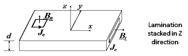
Additional Core Loss Due to Flux Normal to Laminations
When the lamination model is used in the Maxwell 3D transient solver, an additional eddy current component of core loss will be automatically calculated due to the normal component of flux (Bn) on the lamination stack and will be added to the total core loss, if conductivity > 0 has been specified in the material manager. The basic idea of the algorithm for considering this additional eddy current component of core loss is to force induced eddy current only occurring in the plane of lamination by introducing anisotropic conductivity.
To compute this additional core loss component:
- The material conductivity, which is taken from the project material library (not from the core loss input panel), must be specified as non-zero.
- The object must be defined as a lamination.
- The eddy effect must always be turned off for laminated objects.
- Core Loss Setting should be activated on the Set Core Loss panel, General tab under Excitations.
- A fine mesh in the object is required to accurately calculate the additional eddy current loss due to this effect.
- For adjacent lamination stacks that are touching, insulating boundaries should be applied to prevent eddy currents from circulating between the stacks.
Additional Core Loss Due to Manufacturing Processes
Lamination steel is cut to the final shape by manufacturing processes such as punching or laser cutting. These processes deteriorate the magnetic properties of the material due to the plastic deformation and residual stress near the cut edge that directly cause core loss increase in the deformation region. These losses can be taken into account for the accurate prediction of the core losses using the Equiv. Cut Depth property value.
To compute this additional core loss component:
- The Edge Cut Based mesh operation must be specified.
- The Composition property for the assigned material must be set to Lamination.
- The Equiv. Cut Depth material property must be set to a value greater than zero (default is 1 mm).
Related Topics
Calculating Properties for Core Loss (BP Curve)
Core Loss Coefficients for Electrical Steel
Core Loss Coefficient Extraction from Single-Frequency Loss Curve
Core Loss Coefficient Extraction from Multi-Frequency Loss Curves
Core Loss Parameter Extraction for Power Ferrite Materials