
Lamination Modeling
Lamination modeling allows you to specify a stacking factor and stacking direction, which represents the direction perpendicular to the plane of the lamination. Cartesian, cylindrical, or spherical coordinate systems can be used to specify the stacking direction.
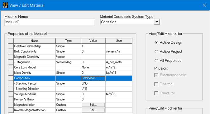
This lamination model is an alternative way of specifying anisotropic behavior when using laminations (which is a special case that is frequently done). For the frequently encountered case of isotropic laminations (where the global model is anisotropic due to the existence of laminations but the laminations themselves are isotropic), the above picture shows a possible setup. Choose a nonlinear behavior for the material of the lamination with a user specified B-H curve, while the global anisotropy is modeled by specifying a stacking factor and the stacking direction, which is perpendicular to the plane of laminations. In this way, Maxwell can consider a global anisotropy with two orientations — one in the plane of the lamination, and the other in the corresponding orthogonal direction.
When a stacking factor (SF) is used, users need to modify the electrical steel core loss coefficients based on the stacking factor as shown below. As the stacking factor decreases < 1, the core loss coefficients increase.
Kh_scaled = Kh / SF
Kc_scaled = Kc / SF
Ke_scaled = Ke / sqrt(SF)