
Setting Coordinate Systems
The modeler has several types of coordinate systems that enable you to easily orient new objects:
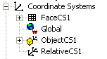
- a global coordinate system
- a relative coordinate system
- a face coordinate system
- an object coordinate system
Every coordinate system (CS) has an x axis that lies at a right angle to a y axis, and a z axis that is perpendicular to the xy plane. The origin (0,0,0) of every CS is located at the intersection of the x, y, and z axes. The default Global coordinate system and any additional coordinate systems that you create for a project appear in the History tree of the modeler window.
- The global coordinate system (CS) is the fixed, default CS for each new project. It cannot be edited or deleted.
- A relative CS is user-defined. Its origin and orientation can be set relative to an existing CS. A relative CS enables you to easily draw objects that are located relative to other objects. If you modify a relative CS, all objects drawn on that CS will be affected and change position accordingly. You can define a relative CS to be offset and/or rotated from an existing CS. This feature provides a way for objects made of the same anisotropic materials to have different orientations.
When you set a new relative coordinate system, you specify whether to express the coordinates as Absolute or Relative Coordinates. Absolute uses the specified values in terms of the global coordinate system. Relative interprets the values as differences from the current working CS.
You have choices for expressing the coordinates as Cartesian, Cylindrical, or Spherical. These are evaluated as Cartesian for the coordinate system properties.
- A face CS is also user-defined. Its origin is specified on a planar object face. Face CSs enable you to easily draw objects that are located relative to an object’s face.
-
An Object CS is user-defined as attached to a specific object.
Switch between global, relative, object, and face CSs by changing the working CS: click the CS you want to use in the history tree. The working CS is indicated by a red W that appears at the lower-left corner of the CS name in the history tree. The Properties dialog box lists the CS associated with an object as the Orientation. By default, this is Global, but if you have created the object under a different coordinate system, that will be the orientation. You can click on the current orientation to see a drop down list of other orientation that you can assign for an object.
User-defined CSs are saved with the active project. When you open a project, it uses the CS designated as working CS when you last saved.
Related Topics
Creating a Relative Coordinate System
Creating a Face Coordinate System
Setting the Working Coordinate System