Current Limitations on PTD/UTD Wedge Generation/Editing
Situations where wedges cannot be generated:
Light Weight Imported STL Geometries: STL models imported as light weight geometries are currently not supported for interactive wedge editing (as of R24.1).
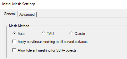
In the Initial Mesh Settings for SBR+ Solution type or for HFSS with Hybrid and Arrays that include SBR+ regions, you can turn off tolerant meshing.
In these cases, wedges cannot be generated at some locations where different geometry bodies are making contact. More specifically, these are locations on geometries where the mesh edges are in contact with three or more mesh faces.
This includes both cases where geometries are merely touching and cases where geometries are outright intersecting.
This includes three dimensional bodies contacting three dimensional bodies, three-dimensional bodies contacting plane objects, and plane objects intersecting plane objects:
Note that on an edge where two plane objects touch (but not intersect), wedges can be generated however the processed wedge angles may be misleading (see next section).
With tolerant meshing, wedges can be generated at points of contact between different bodies. However, these wedges may not have physically correct wedge angles (see next section).
Situations where visualized wedge angles can be misleading
With tolerant meshing, wedges can be generated at the locations of contact between geometries where it would otherwise not be possible with rigorous meshing. However, often in these cases the generated wedges will be processed with interior wedge angles different from the ones visualized in the model window and as such can lead to unphysical simulation results.
As objects are meshed independently of one another with tolerant meshing, wedge angles on objects will not consider any contact with other objects. This issue is illustrated by the following examples:
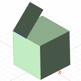
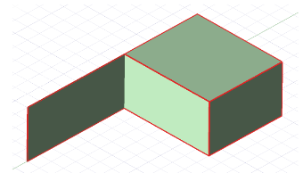
In this example a plane contacts a cube at a 45°angle and a wedge is generated on the edge of contact. From the model window it may appear that this wedge will be simulated with an angle of 45° however depending on whether the edge of the plane or the edge of the cube was selected, a wedge angle of 90° or 360° will instead be used by the solver.
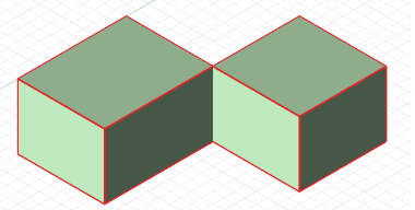
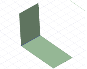
In the next example two planes meet at a 90° angle and a wedge is generated on the edge of contact. Similar to the previous example, the wedge appears to have an angle of 90° in the model window but the solver will actually consider the angle to be 360°. Note that in this case, the user can unify the two planes to get the correct 90°.
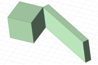
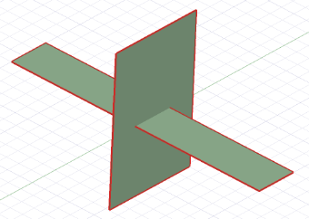
In the final example a cube contacts a rectangular solid at an angle of 30° from the perspective of the image. As before the wedge generated on the edge of contact will be simulated with an angle of 90° instead of the 30° or 150° which may be intended by the user.