
Drawing a Polyline
A polyline is a single object that includes any combination of straight line, arc line, or spline segments. The endpoint of one segment is the start point for the next segment. Use the shortcut menu's Set Edge Type commands to switch between straight line, arc line, or spline segments while drawing a polyline.
Before drawing a polyline, determine how closed polylines will be handled in the 3D Modeler options, as follows:
Using the menu bar, click Tools > Options > General Options. In the Options dialog box that appears, choose 3D Modeler > Operation from the tree on the left side. Then, in the Polyline Creation section of the operation options, select or clear the Automatically cover closed polylines check box.
If checked, closed polylines become sheet objects and are listed under Sheets in the History Tree. If unchecked, closed polylines are listed under Lines in the History Tree.
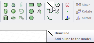
- From the menu bar, click Draw>
 Line or, on the Draw ribbon tab, click the Draw line icon:
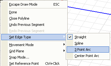
- Right-click in the 3D Modeler window to access the shortcut menu, and then point to Set Edge Type.
- Click Straight, Spline, 3 Point Arc, or Center Point Arc, depending on which type of polyline segment you want to draw.
- Depending on your selection in the previous step, do one of the following:
- If you clicked Straight, follow the procedure for drawing a straight line.
- If you clicked Spline, follow the procedure for drawing a spline.
- If you clicked 3 Point Arc, follow the procedure for drawing a three-point arc line.
- If you clicked Center Point Arc, follow the procedure for drawing a center-point arc line.
- Repeat steps 2 and 3 for each segment of the polyline object. The endpoint of the previous segment serves as the start point for the next segment.
The shortcut menu lets you do the following for each segment:
Undo Previous Segment or Redo Previous Segment.
- Complete the polyline in one of the following ways:
- Double-click the endpoint of the final segment.
- Click Done on the shortcut menu.
Note:To connect the polyline's start and endpoints, click Close Polyline on the shortcut menu.
If the Modeler option for editing properties of new primitives is checked, the Properties dialog box appears, in which you can modify the object's attributes by
- Click OK.
If you select a polyline in the History Tree, you can use the Measure mode to see the total length.