
Drawing a Center-Point Arc Line
In the modeler, a center-point arc line segment is an arced line defined by a center point, start point and angle. Use the Draw > Arc > Center Point command to create a polyline object with one or more center-point arc line segments. Before you draw a center-pint arc line, you can specify the coordinate system, and you can set the drawing plane as Z, Y, or Z, or you can edit the plane in the properties.
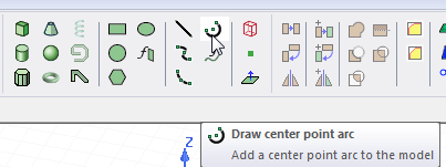
- From the menu bar, click Draw> Arc>
 Center Point or, on the Draw ribbon tab, click the Draw center point arc icon:
- Select the center point of the arc in one of the following ways:
- Click the point.
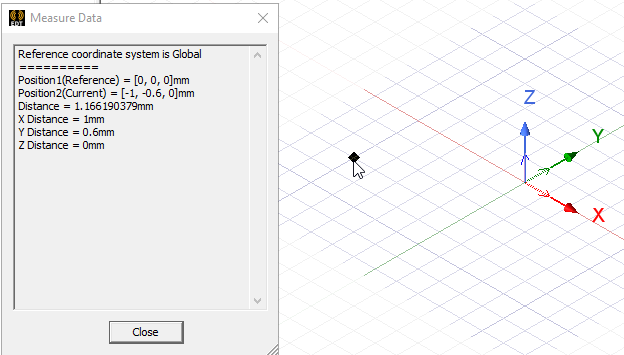
- Type the point's coordinates in the text boxes in the status bar.

- Click the point.
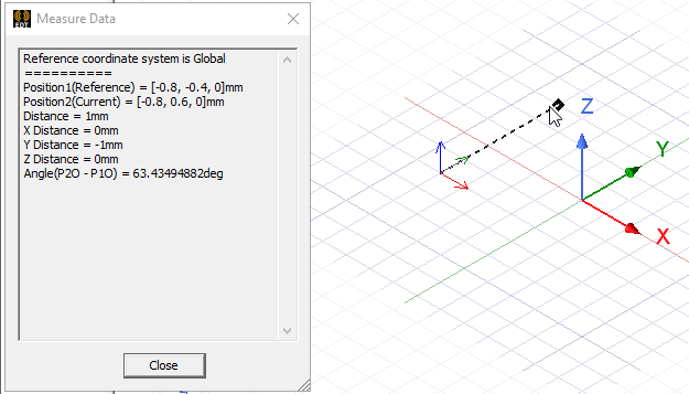
- Select the start point, or radius, of the arc by clicking the point or typing the coordinates in the text boxes in the status bar.
To delete the last point that was entered, click Undo Previous Segment on the shortcut menu. After using the undo feature, you can also use Redo Previous Segment on the shortcut menu.
To delete all points and start over, press Esc or click Escape Draw Mode on the shortcut menu.
- Sweep the angle, or endpoint, of the arc by clicking the point or typing the coordinates in the text boxes in the status bar.
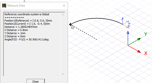
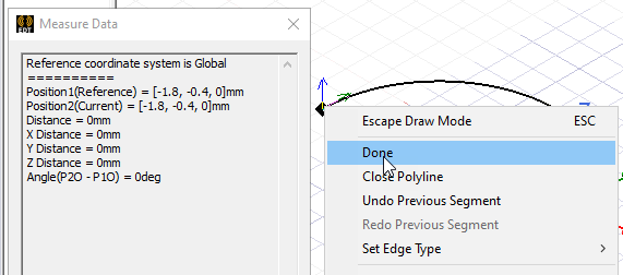
- If the endpoint is the last point of the polyline object, double-click the point to complete the polyline or click Done on the shortcut menu.
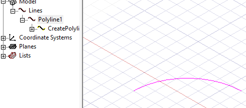
If the Modeler option for editing properties of new primitives is checked, the Properties dialog box appears, enabling you to modify the object's attributes. The new polyline appears in the modeler window and in the History tree.
- Click OK.
Note:
While drawing a polyline, you can switch between arc line, straight line, or spline segments using the Set Edge Type commands on the shortcut menu.