
Drawing a Line Segment
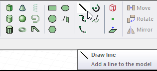
To create an object with one or more straight line segments, use the Draw > Line command.
- From the menu bar, click Draw>
 Line or, on the Draw ribbon tab, click the Draw line icon:
- Select the first point of the line in one of the following ways:
- Click the point in the Modeler window, checking the Measure Data dialogue for the precise coordinates.
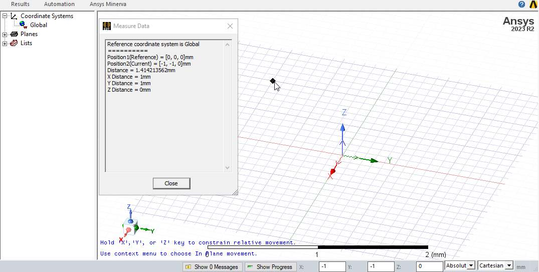
- You can accept the first point or change it by editing its coordinates in the X, Y, and Z boxes in the status bar. Note that the Status bar includes selections for Absolute or Relative Coordinates, as well as for Cartesian, Cylindrical and Spherical Coordinates.
To delete the last point that was entered, click Undo Previous Segment on the shortcut menu. After using the undo feature, you can also use Redo Previous Segment on the shortcut menu.
- Click the point in the Modeler window, checking the Measure Data dialogue for the precise coordinates.
- Select the next point of the line by clicking the point or typing the coordinates in the text boxes in the status bar.
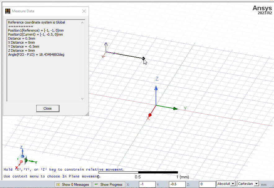
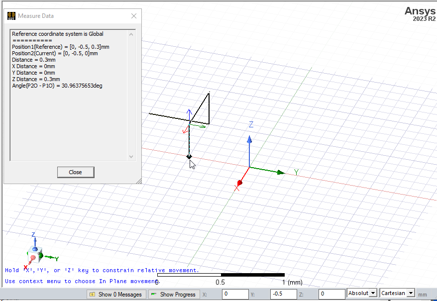
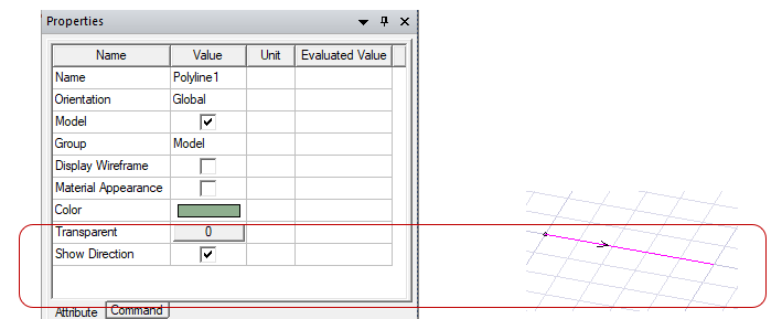
The endpoint serves as the start point for a subsequent line segment. You can specify the plane through which the line passes by selecting the X, Y, or Z keys to constrain movement. For example, the following figure shows a line with five points that includes X, Y, and Z movements.
To delete all points and start over, press Esc or click Escape Draw Mode on the shortcut menu.
- Complete the line in one of the following ways:
- Double-click the endpoint.
- Click Done on the context (right-click) menu.
- Press Enter.
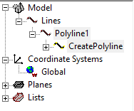
The new line appears selected in the Modeler window and shown in the History tree.
If the Modeler option for editing properties of new primitives is checked, the Properties dialog box appears, in which you can modify the object's attributes by editing the object's properties. You can also do this through the docked Properties window.
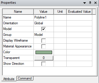
Those listed under the Command tab describe the commands used to create the object. These commands also appear in the History Tree. The properties listed as line attributes include Name, Orientation, whether a Model object, whether to Display Wireframe, Color, Transparency, and whether to Show Direction as arrows. The Show Direction property is most helpful to unambiguously show the line start orientation when
-
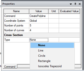
The Command tab Properties includes the Coordinate System that applies to the line, the number of points and curves, as well as the ability to assign a specific Cross Section to the line.
- If you created the line with the Modeler option for editing properties of new primitives, click OK to close the Properties dialog box.
Note: While drawing a polyline, you can switch between straight line, arc line, or spline segments using the Set Edge Type commands on the shortcut menu.