


From the properties dialog of the FE body, the initial velocity and options for analysis can be modified as shown in the figures below. Material parameters such as the body type and mass properties are defined in the figure and table below.
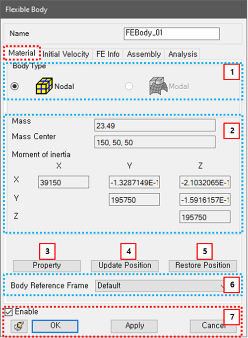
Figure 3.141: Description of Material parameters in the FE body properties dialog
| Parameter | Symbol | Description | Dimension (Range) |
| 1. Body Type | N/A | Use to select the type of the FE body. When this is set to Nodal, the body will be treated as a Nodal FE Body. When the type is Modal, the body will be treated as a Modal FE Body. | N/A |
| 2. Material | N/A | Use to display the mass, center position of mass and mass moment of inertia of the body. The mass properties can be defined in the Mesh file. See Nodal FE Body. |
For Mass: Mass (Real>0) For Mass Center: Lengths (Real) For Moment of Inertia: Mass*Length^2 (Real) |
| 3. Property | N/A | Use to display the finite element properties used in the FE body. These properties can be defined in the Mesh file. See Nodal FE Body. | N/A |
| 4. Update Position | N/A | Use to update the nodal positions to the deformed positions by importing a DFN file. The deformed position and plastic strain are defined in the DFN file which is created by the Postprocessor using simulation results. See the Export of FE Body Position in the Postprocessor User Guide. This option is useful to show the initial deformation of an FE body and is also available for a Nodal FE Body. | N/A |
| 5. Restore Position | N/A | Use to restore the deformed nodal positions to the original positions. | N/A |
| 6. Body Reference Frame | N/A |
Use to change the nodal body reference frame. See equations Equation 3–15 and Equation 3–16 in Nodal FE Bodies for more details. When the FE body rotates, it is useful to improve convergence by setting the body reference frame as the action or base marker of the Revolute Joint or a marker on a Node on the axis of rotation. You should set the body reference frame at a position where the deformation is small and does not vibrate. In the case of a nodal body, the marker on the connector of the or force connected to this body, or the marker on a defined on this body can be selected as the body reference frame. Setting as the body reference frame is recommended when there is no connector connected to the body. Note that using Marker on Node as a body reference frame may increase the stiffness of the element containing the selected node. The body reference frame becomes read only because it must be defined from the .dfmesh file. | N/A |
| 7. Control buttons | N/A | If all necessary parameters are set, these buttons are enabled. For more information about the control buttons, refer to Entity Properties Access and Modification. | N/A |
Parameters for initial velocity are defined in the Initial Velocity tab. Their definitions are same as for Figure 3.18: Initial Velocity tab in the of Solid Body properties dialog.
The FE Info tab lists information about the FE body, as shown in the figure and table below.
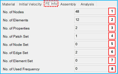
Figure 3.143: Description of FE Info parameters in the FE Body properties dialog
| Parameter | Symbol | Description | Dimension (Range) |
| 1. No. of Nodes | N/A | The number of nodes which can be defined in the FE data file. | N/A |
| 2. No. of Elements | N/A | The number of finite elements which can be defined in the FE data file. | N/A |
| 3. No. of Properties | N/A | The number of properties for the finite elements which can be defined in the FE data file or Mesh. | N/A |
| 4. No. of Patch Set | N/A | The number of Patchsets which can be defined in the Mesh. | N/A |
| 5. No. of Node Set | N/A | The number of Nodesets which can be defined in the Mesh. | N/A |
| 6. No. of Edge Set | N/A | The number of Edgesets which can be defined in the Mesh. | N/A |
| 7. No. of Element Set | N/A | The number of element sets which can be defined in the FE data file. | N/A |
| 8. No. of Used Frequency | N/A | The number of modes which belong to the FE body. They can be defined in the Mesh and are available in the modal FE body. | N/A |
The Assembly tab shows the Mesh file information as shown in the figure below and in the following table.
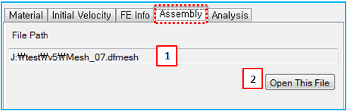
Figure 3.145: Description of Assembly parameters in the FE Body properties dialog
| Parameter | Symbol | Description | Dimension (Range) |
| 1. File Path | N/A | Displays the path and name of the imported mesh file. | N/A |
| 2. Open This File | N/A | Use to open the mesh file. | N/A |
The Analysis tab lists the analysis parameters as shown in the figure below and in the following table.
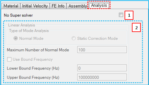
Figure 3.147: Description of Analysis parameters in the FE body properties dialog
| Parameter | Symbol | Description | Dimension (Range) |
| 1. No Super solver | N/A | Use to set the No Super Solver option. When selected, the super solver is not used for the FE body. This option is useful for an FE body with a large deformation or rotation and is available for a nodal FE body. | N/A |
| 2. Linear Analysis | N/A | Use to display the parameters for the body eigenvalue analysis. Their definitions are introduced in Body Eigenvalue Analysis Properties. | N/A |