


As shown in the figure below, the Maximum Number of Normal Mode property, the Use Bound Frequency property, and several parameters for the simulation can be defined in the dialog. The properties are similar to those of the simulation configuration and are described in the table below.
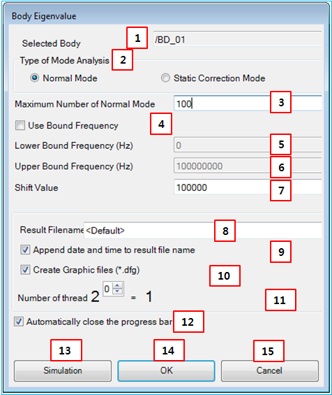
Figure 9.36: Body Eigenvalue Analysis properties
| Feature | Description | Dimension (Range) |
| 1. Selected Body | Use to select a solid body and display its name in the subsystem. For the mesh, this content isn't supported. | N/A |
| 2. Type of mode analysis | Use to define the analysis type for the body eigenvalue analysis. When "Normal Mode" is selected, the eigenvalue of the body is calculated with the free-free boundary condition. When "Static Correction Mode" is selected, the eigenvalue of the body is calculated while including the static correction mode. The static correction mode is defined as a static deformation due to imposing unit displacement on the nodal coordinate in the boundary which is defined by Faceset or Nodeset and zero displacements on the remaining nodal coordinates in the other boundary. | N/A |
| 3. Maximum Number… | Use to set the maximum number of normal mode. For more information, see this content of Eigenvalue Parameters for Simulation Configuration. |
N/A (Integer>0) |
| 4. Use Bound Frequency | Use to determine whether use the bound frequencies. For more information, see this content of Eigenvalue Parameters for Simulation Configuration. |
N/A (0<Real≤1) |
| 5. Lower Bound… | Use to set the lower bound frequency in Hz. For more information, see this content of Eigenvalue Parameters for Simulation Configuration. |
Hz (Real>0.0) |
| 6. Upper Bound… | Use to set the upper bound frequency in Hz. For more information, see this content of Eigenvalue Parameters for Simulation Configuration. |
Hz (Real>0.0) |
| 7. Shift Value | Use to set the shift value for the stability of the eigenvalue analysis. For more information, see this content of Eigenvalue Parameters for Simulation Configuration. |
N/A (Real>0.0) |
| 8. Result filename | Use to define the file name and path for Simulation Output Files. | N/A |
| 9. Append… | Use to append the date and time to the result file name. For more information, see this content of Simulation Configuration Parameters. | N/A |
| 10. Create graphics files | Use automatically to create the DFG, DFR and DFM files for the Motion Postprocessor. For more information about the files, see Simulation Output Files. | N/A |
| 11. Number of threads | Use to define the power to calculate the number of threads for the shared memory parallel processing. The number of threads is calculated as 2^n. |
N/A (Integer>0) |
| 12. Automatically close… | Use to close the progress bar when the simulation is stopped. | N/A |
| 13. Simulate | Close the simulation configuration dialog with saving the changed information, run the simulation and open Motion/Postprocessor after the simulation. | N/A |
| 14. OK | Close the simulation configuration dialog with saving the changed information. | N/A |
| 15. Cancel | Close the simulation configuration dialog without saving the changed information. | N/A |