


You can use geometry-based Named Selections to inspect only a portion of your model's total mesh. Although this feature is available regardless of mesh size, it is most beneficial when working with a large mesh (greater than 5 - 10 million nodes).
After you have designated a Named Selection group, you can use any of the following features to assist you:
Showing the Mesh
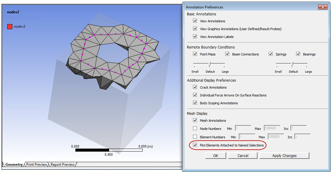
By setting the Plot Elements Attached to Named Selections option in the Annotation Preferences, you can view the elements for all items in the Named Selection group. For node-based Named Selections, this option shows the full elements, while for face or body Named Selections, this option shows just the element faces.
Note: This option does not affect Line Bodies, and you must have the Show Mesh button toggled off to view the elements in the Named Selection.
An example is shown below of a node-based Named Selection.
Showing Annotations
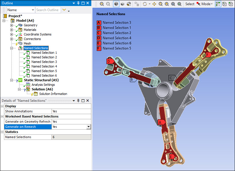
As illustrated below, selecting the Named Selection folder displays all of the user-defined Named Selection annotations in the Geometry window. This display characteristic can be turned or using the Show Annotations category in the Named Selections Details view.
Selecting an individual Named Selection displays the annotation specific to that Named Selection in the Graphics pane.
You can also toggle the visibility of mesh node annotations and numbers in the annotation preferences. For more information, see Specifying Annotation Preferences.
Displaying Individual Named Selections in Different Colors
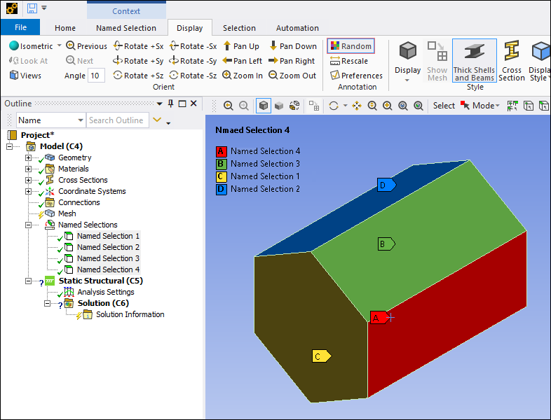
By default, Named Selections are shown in red. You can use the Random Colors button on the Display tab to display each named selection with a random color at each redraw.
Setting Visibility
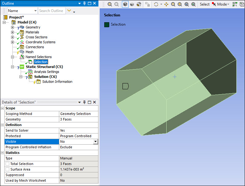
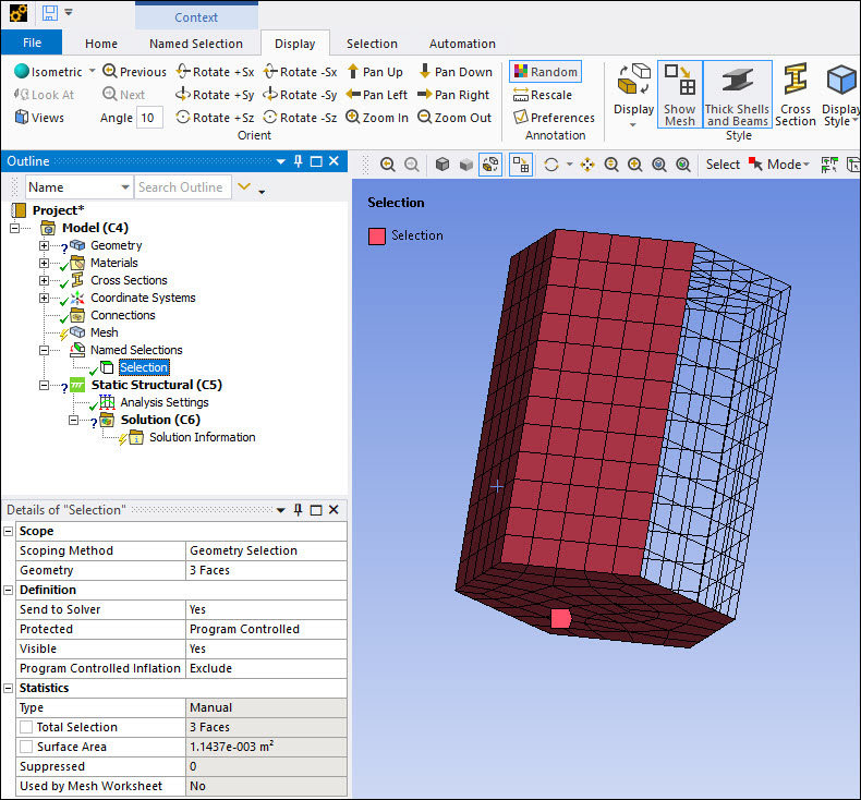
By setting the Visible object property in the Details view of an individual Named Selection object to , the Named Selection can be made invisible, meaning it will not be drawn and, more importantly, not taken into consideration for picking or selection. This should allow easier inspection inside complicated models having many layers of faces where the inside faces are hardly accessible from the outside. You can define Named Selections and make them invisible as you progress from outside to inside, similar to removing multiple shells around a core. The example shown below displays the Named Selection 3 Faces with the Visible property set to .
Displaying an Enhanced View of Meshed Items
Display your model in Wireframe mode by selecting the Wireframe option in the Display drop-down menu on the Display tab or by selecting the option on the Graphics Toolbar. Then, open the Annotation Preferences dialog box by selecting the option in the Annotations group. Check the option. This feature displays the meshed entities of your Named Selection only, as illustrated below.
Characteristics and Notes
The Visible object property is the same as the Hide Face(s) option in the right mouse button context menu. These options will hide only the specified Named Selection. This behavior differs from that of the Hide Bodies in Group and Suppress Bodies in Group options, which hide or suppress the full body containing a given Named Selection.
When a Named Selection's Visible setting is set to :
Only the faces from that Named Selection are not drawn; the edges are always drawn.
The Named Selection will not appear in any drawing of the geometry (regardless of which object is selected in the tree).
Unless...
The Named Selection is displayed as meshed, it displays the mesh, but only if you have the Named Selection object or the Named Selectionsfolder object is selected in the tree. This behavior is the same as the behavior of the red annotation in the Geometry window for Named Selections (that is, the annotation appears only when the current selected object is the specific Named Selection object or the Named Selectionsfolder object).
After at least one Named Selection is hidden, normally you can see the inside of a body, so displaying both sides of each face is enabled (otherwise displaying just the exterior side of each face is enough). But if a selection is made, the selected face is always displayed according to the setting in the Options preference under Mechanical > Graphics > Highlight Selection. Single Side is the default setting. It can be one side or both sides.
If the Wireframe display option is used and Show Mesh is Yes, any face selected is displayed according to the Highlight Selection property of the Options dialog under Mechanical > Graphics. Single Side is the default setting. It can be one side or both sides.