


For Bushing, General Joints, and Radial Gaps (RBD only), Mechanical enables you to solve analyses with linear and nonlinear joint stiffness using the features of the Worksheet. For these joint types, the Worksheet provides the entry options for and data.
Linear or nonlinear stiffness and damping behavior is associated with the free or unrestrained components of relative motion of the joint elements. That is, the DOFs are free. For a General Joint, you must specify the DOFs as in order to make entries in the Worksheet matrix.
Element Specification
Generally, Joint Stiffness calculations use the joint element MPC184. See the Mechanical APDL Element Reference for additional information as well as the Mechanical APDL Material Reference section for MPC184 Joint.
When you specify a Bushing joint with the formulation, the application uses the bushing element COMBI250. See its Mechanical APDL Element Reference section for additional information.
Important: For the MPC184 and COMBI250 element types, the application may transform the input matrix coefficients based on the sequence of the following coordinate system and node rotation definitions. The application first uses:
The to apply rotation.
Then nodal rotations defined on associated Remote Points (Reference and Mobile). For example, the NROTAT command rotates nodal coordinate systems into the active system.
Note: The rotation from these remote points modifies the element matrix.
Lastly, the application performs the normal processing sequence for rotations.
Recommendation: Ansys recommends that you specify the same coordinate system for Element Coordinate System, Reference Coordinate System, and Mobile Coordinate System properties in case there is a relative rotation between the Element Coordinate System and either the Reference Coordinate System or Mobile Coordinate System. In addition, you need to verify proper rotation as well as results.
Linear Joint Stiffness
In the case of linear stiffness or linear damping, the values are specified as coefficients of a 6 x 6 elasticity table matrix. Joint Stiffness calculations use the joint element MPC184 and therefore only the appropriate coefficients of the stiffness or damping matrix are used in the joint element calculations.
Nonlinear Joint Stiffness
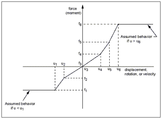
For nonlinear joint stiffness, relative displacement (rotation) versus force (moment) values are calculated. For nonlinear damping behavior, velocity versus force behavior is specified. You specify nonlinear damping behavior by supplying velocity versus damping force (or moment). The following illustration represents a nonlinear stiffness or damping curve. Note that the Mechanical APDL solver and the Rigid Dynamics Solver assume that there is no added stiffness past the extents.
See the Material Behavior of Joint Elements topic of the Connecting Multibody Components with Joint Elements section in the Mechanical APDL Multibody Analysis Guide for additional details about how this feature related to the Mechanical APDL.
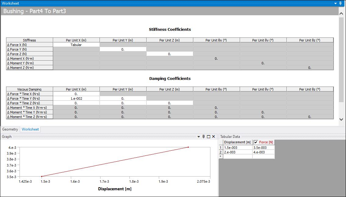
Worksheet
Using the Worksheet, you can define Stiffness Coefficients in or format.
Important: You cannot edit entries that depend upon an angle unit when the active unit is set to degrees (°). To modify these values, change the active angular unit to Radians.
Nonlinear Joint Stiffness is supported by data entries only and the entries must be made diagonally. In addition, Damping Coefficients entries only support constant values.
Note:
The Mechanical APDL solver does not support a mixture of and data entries in the Stiffness Coefficients matrix. That is, you cannot mix linear and nonlinear stiffness.
For a linear analysis, such as a Modal analysis, it is recommended that you specify constant values in the Stiffness Coefficients matrix. In the event you do specify stiffness values through Tabular Data (Displacement vs Force), the application uses the stiffness defined by the slope of the curve at origin (0,0). Also note that if the Tabular Data:
Starts with the entry 0,0 (Displacement, Force), the application uses the next non-zero entry in the table to compute the stiffness and then uses it throughout the analysis.
Starts with a non-zero entry after the origin (0,0), the application uses zero as the stiffness value for the entire analysis.
The Ansys Rigid Dynamics Solver does support the combination of and data entries.
The Report Preview feature does not display table entries from the nonlinear joint stiffness matrix.
The Ansys Explicit Dynamics solver does not support tabular input (and therefore nonlinear stiffness behavior).
For the Ansys Rigid Dynamics Solver, the use of non-symmetric force/displacement (or torque/rotation) curves is not recommended as it may lead to incorrect results.