


Use the Fracture Tool object to insert and then define fracture results for the crack types specified in your analysis. All fracture results are child objects of the Fracture Tool. Use its properties to evaluate result data.
Go to a section topic:
Define a Fracture Tool
To define a Fracture Tool:
Select the Solution object, open the drop-down menu from the Solution Context tab, and select the Fracture Tool option. Based on the settings of the Fracture Controls of the Analysis Settings object, a result object, such as SIFS (K1), is automatically included under the Fracture Tool.
Set the Scoping Method property to (default). To read results into the application using the option, see the Extract Fracture Results from a Result File topic below.
Specify the Crack Selection Mode property as either (default) or . When you specify , the child result objects of the tool display the Tabular and Graph Data category. Use this to further select specific crack(s) of interest that are available in your model. See the Defining a Fracture Result topic below.
For the option, the following additional properties display:
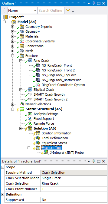
Crack Selection: Specify the crack on which to evaluate results.
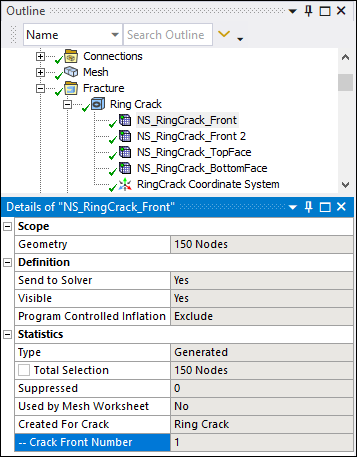
Crack Front Number: Specify the crack front(s) on which to evaluate results. Options include (default), which is equal to setting the property to zero (0) or you can enter a specific Crack Front Number (contained in the Details of the crack front named selection object) to evaluate results for that crack front only.
For the above crack front, the Fracture Tool could be specified as shown below.
Define Fracture Results
Review the Methods Used for Calculating the Fracture Parameters topic in the Understanding the Fracture Parameters section of the Mechanical APDL Fracture Analysis Guide for more information about fracture results.
To define a fracture result:
From the Fracture Tool Context tab, select desired results. Options include:
inserts a Mode 1 Stress Intensity Factor result.
inserts Mode 2 Stress Intensity Factor result.
inserts Mode 3 Stress Intensity Factor result.
J-Integral (JINT) inserts a J-Integral result.
Note:The computation for the J-Integral result includes the effect of body forces.
The application enables you to compute the Equivalent SIFS Range result in addition to one fracture parameter result (SIFS results or J-Integral) when the SMART Crack Growth associated to the crack is of type (Crack Growth Option = ).
inserts Mode 1 Energy Release Rate result.
inserts Mode 2 Energy Release Rate result.
inserts Mode 3 Energy Release Rate result.
inserts Total Energy Release Rate result.
Material Force>Material Force (X Axis) inserts Total Material Force result in the X Axis of the local crack front node coordinates.
Material Force>Material Force (Y Axis) inserts Total Material Force result in the Y Axis of the local crack front node coordinates.
Material Force>Material Force (Z Axis) inserts Total Material Force result in the Z Axis of the local crack front node coordinates.
T-Stress
C*-Integral
Note: The C*-Integral result is only valid when the analysis includes a creep material, and the property of the Creep Controls is set to .
Equivalent SIFS Range (available when specified crack is associated with Fatigue SMART Crack Growth)
Tip: You can use the Type and Subtype properties of a result to change result parameters as desired.
Define the properties of each result. Options specific to fracture results include:
Contour Start: Specifies the first contour number for which the result will be plotted in the graph and displayed in the tabular data. The value must not be greater than the value of Contour End. This option is applicable to SIFS, JINT, Material Force, T-Stress and C*-Integral types of fracture result.
Contour End: Specifies the last contour number for which the result will be plotted in the graph and displayed in the tabular data. The value must not be greater than value of the Solution Contours option specified for the associated crack object. Since the maximum of 10 contours can be plotted in Graph window at one point of time, the difference between Contour End and Contour Start must not be greater than 9. This option is applicable to SIFS, JINT, Material Force, T-Stress and C*-Integral types of fracture result.
Active Contour: Specifies the contour number for which the results are plotted in the Geometry window. By default, it takes the "Last" value as in the Contour End property. This option is applicable to the SIFS, JINT, Material Force, T-Stress and C*-Integral result types. The Geometry window displays the graphical result for the active contour. The "1" in the Geometry window indicates the start of the crack front, while "3" indicates the end of the crack front.

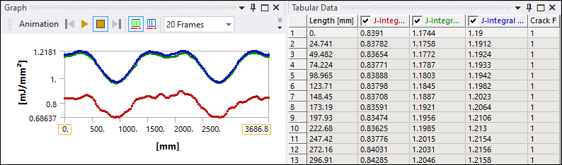
The results are plotted in the Graph window for all contours, starting from the Contour Start value and ending at the Contour End value. The X axis in the Graph window indicates the distance along the crack front. The start of the crack front has a value of zero, and the end of the crack front has the maximum value. The Tabular Data window displays the data points in a table format.
Note: When the Crack Selection Mode property of the Fracture Tool is set to , and more than one crack is defined in the model:
The Contour Start and Contour End properties are not available.
If the Active Contour property is set to , it uses the lowest solution contour value of all the cracks to compute the result.
For information on other Details options, see Results and Result Tools (Group) object reference section.
Extract Fracture Results from a Result File
When you have saved a results file (file.rst) from another fracture analysis, you can read this file into a different analysis and extract the result data with a Fracture Tool. Note the following requirements:
For a Pre-Meshed Crack, you can evaluate the fracture results and probes without defining the crack in the new analysis, but with similar boundary conditions.
For all other crack types, your analysis must include a defined Fracture folder, a matching mesh (including crack mesh), as well as defined boundary conditions.
Use the following steps to specify a Fracture Tool and to extract the fracture results and probes from the result file.
Read the results file into your analysis. As needed, review the Writing and Reading the Mechanical APDL Application Files section.
Select the Solution object, open the drop-down menu from the Solution Context tab, and select the Fracture Tool option. Based on the settings of the Fracture Controls of the Analysis Settings object, a result object, such as SIFS (K1), is automatically included under the Fracture Tool.
Set the Scoping Method property to .
From the Fracture Tool Context tab, select and insert desired results.
From the drop-down list of the Solver ID property, select the appropriate solver ID value for each result. You can now evaluate the specific results.