The Composite Failure Tool is a post-processing option that you can use for composite ply structures that were modeled using Ansys Composite PrepPost (ACP).
This section addresses the following topics:
Overview
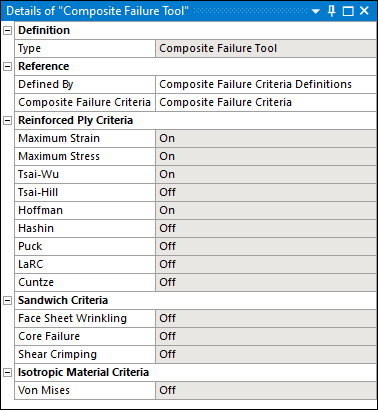
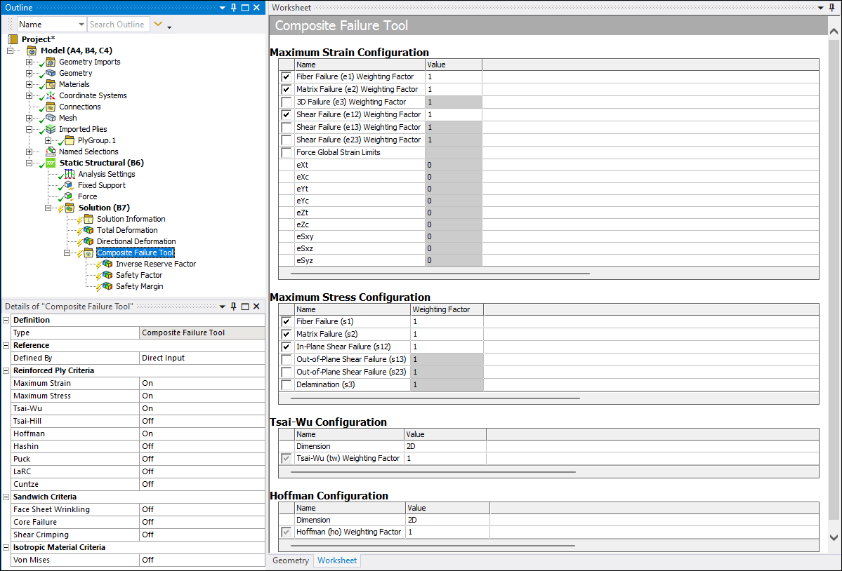
This tool provides result data that corresponds to that of the failure definition in ACP Post. In addition, and as illustrated below, the Details properties for the object provide a set of failure criteria and functionality. You enable these failure criteria using the properties of the Reinforced Ply Criteria category (see Composite Failure Tool Result Objects). The Worksheet provides additional details for each criteria enabling you to make further specifications.
The properties of the Composite Failure Tool enable you to configure your own combined failure criteria for the strength assessment of composites. Both established and basic as well as recent and advanced failure criteria are included in the program and you can combine them with the goal to incorporate all relevant failure modes which turn up in a composite structure. This helps to design robust structures and to work efficiently. A discussion related to the best practices for using this tool is available in the Guide to Composite Failure Criteria topic in the Ansys Composite PrepPost User's Guide.
Result Types
The Composite Failure Tool supports the following result objects:
- Safety Factor (SF)
This result type is an indication of the margin to failure. That is, the applied load multiplied by the safety factor determines the failure load. Failure is experienced when you have a Safety Factor less than 1.
SF x F applied = F f
Safety Factor values that are greater than one indicate a positive margin to failure and values less than one indicate a negative margin. Safety Factor values are always greater than zero.
- Inverse Reserve Factor (IRF)
This result type is an inverse margin to the Safety Factor. The failure load can be defined as the load value divided by IRF. Failure is experienced when you have an Inverse Reserve Factor greater than 1.
IRF = 1/SF
The critical values of reserve factors lie between zero and one, whereas the non-critical values range from one to infinity. Whether the results are shown in numeric form or as contour plots, the non-critical values tend to be emphasized in comparison to critical values.
- Safety Margin
The Safety Margin result is obtained from the safety factor. Failure is experienced when you have a Safety Margin less than 0.
SM = SF - 1
A positive safety margin indicates the relative amount that the applied load can be increased before reaching failure load. Correspondingly, a negative safety margin indicates how much the applied load should be decreased. Safety margins are typically expressed as percentages.
- User-Defined Results
See the User-Defined Results section of the Mechanical Help.
Also see the Composite Failure Tool (Group) object reference page for additional information about these result types.
Application
To define results using the Composite Failure Tool:
Make sure that your composite analysis is properly defined.
Highlight the Solution object and select Composite Failure Tool from the Toolbox drop-down menu or highlight the Solution object, right-click, and then select > Composites > Composite Failure Tool. The Composite Failure Tool becomes the active object in the tree, it contains an Inverse Reserve Factor result object by default, and the Worksheet displays.
Specify the Defined By property as (default) or . In order to select , you must first specify failure criteria in the Reinforced Ply Criteria category and promote the Composite Failure Tool. This creates the required criteria object and you must specify in the Composite Failure Criteria property that becomes available when you select the option. Review the above Composite Failure Tool Promotion topic as needed.
Specify failure criteria by turning the properties of the Reinforced Ply Criteria category of the Details On or Off. The Worksheet aromatically displays and populates with the criteria that you have specified. You can further customize the criteria using the check boxes available in the Worksheet. In addition, further failure criteria changes can be made in the Worksheet, specifically, Weighting values.
Insert results objects as desired (Inverse Reserve Factor, Safety Factor, and Safety Margin) from the Composite Failure Tool Context tab or using the right-click context menu.
For individual result objects, specify elemental max or ply-wise results using the options of the Sub Scope By property, (default) or . Based on your selection, either or displays in the Display Option property.
The properties Show Critical Failure Mode, Show Critical Layer, and Threshold for Text Visualization are used to configure the overlaid text plot as shown below. The acronyms indicate the failure mode and the indices the critical layer where failure occurs. The text labels are not shown if they are below the defined threshold which is, by default,
0.25. If working with very large models, it is suggested that you set a meaningful threshold so that thousands of text labels do not display. This makes it easier to examine the structure and improves the performance.Show On Reference Surface: Use this property when you import a model from Ansys Composite PrepPost (ACP) that includes a specified Reference Surface. Options include (default) and . When set to , the solid mesh displays the worst failure and mode per solid element. When set to , the result displays the worst failure, per solid stack, on the shell mesh of the specified Reference Surface only.
Composite Failure Tool promotion may occur as desired.
Composite Failure Tool Promotion
The purpose of this feature is to enable you to create and share one or more combinations of failure criteria by using them in various tools or across analyses. Through the promotion feature, as illustrated below, you can promote a defined Composite Failure Tool to the Composite Failure Criteria Definitions object. By default, the promoted object maintains the name of the original object, such as the default tool name, "Composite Failure Tool."
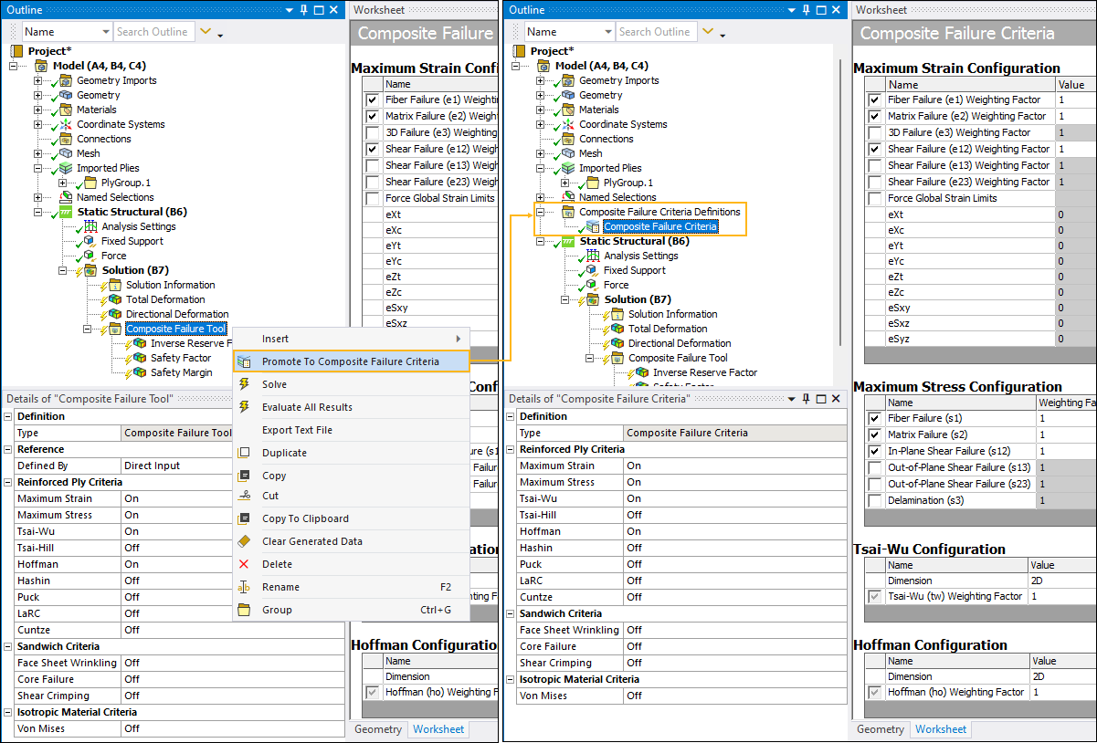
After promotion, the properties of the corresponding Composite Failure Tool object become read only, except for the Defined By and the Composite Failure Criteria properties.