


If your model contains Contact Regions, you can define the contact results listed below under the Solution object by inserting a Contact Tool . See the Reviewing the Results section of the Contact Technology Guide for additional information.
Gap
Penetration
Pressure
Important: The application only reports contact pressure results for corner nodes. However, the possibility exists that the contact element has contact with at least one mid-side node while the corner nodes are not in contact. As a result, the element may have a closed contact status even though the reported contact pressure is zero. To verify the contact status for contact elements in this situation, list the following ETABLE quantities: SMISC,13 (PRES): NMISC,41 (STAT): NMISC,43 (CNFX): NMISC,44 (CNFY): and NIMSC,45 (CNFZ). Also note you can specify these quantities, such as SMISC,13, in a User Defined result using an appropriate Expression (SMISC13).
Frictional Stress: Available only for evaluating contact conditions after solution.
Note:To reflect total contact pressures or frictional stress, you must either set the Behavior option to Asymmetric or Auto Asymmetric, or manually create an asymmetric contact pair.
For node-to-surface contact, Pressure will display zero results. To display the associated contact force, you must insert a user defined result called CONTFORC. This is also the case for the General Axisymmetric feature, which employs node-to-surface contact.
Sliding Distance: Available only for evaluating contact conditions after solution. The total sliding distance (SLIDE) is the maximum total sliding distance (algebraic sum) when the contact status is sticking or sliding (STAT = 2, 3). It contains contributions from the elastic slip and the frictional slip. Elastic slip due to sticking represents the reversible tangential motion from the point of zero tangential stresses. Ideally, the equivalent elastic slip does not exceed the user-defined absolute limit. The higher the tangent stiffness, the smaller the resulting elastic slip. The pair-based elastic slip can be monitored using the Contact Result Tracker.
Fluid Pressure: Fluid penetration pressure (surface-to-surface contact only). Note that command snippets are required to apply the loading to create this result. For more information, see Applying Fluid-Pressure-Penetration Loads in the Contact Technology Guide.
Status. Status codes include:
-3 - MPC bonded contact.
-2 - MPC no-separation contact.
0 - open and not near contact.
1 - open but near contact.
2 - closed and sliding.
3 - closed and sticking.
The labels Far, Near, Sliding, and Sticking are included in the legend for Status.
Note:MPC-based contact definitions use negative values. They indicate the intentional removal of one or more contact constraints to prevent over-constraint.
Contact that has been deactivated via Auto Asymmetric behavior will be displayed with a status of Far-Open. Results for deactivated pairs can be suppressed in the Contact Tool by changing Both to either Contact or Target as necessary.
If you choose to display contact results with a display option other than
Unaveraged, then Mechanical uses all elements in the selected regions to
calculate the result. That is, Mechanical averages contact across regions regardless of whether
you scoped the result via Geometry Selection or via the Worksheet.
For example, if you set the display option to Averaged, then the
displayed result for a node is the average of all values (from all selected elements) at that
node. Contact elements can be coincident, which may be difficult to discern visually, and
Mechanical does not display unaveraged contact results if it detects coincident elements in the
scoping. However, Mechanical calculates and displays averaged contact results for coincident
elements.
In addition, if more than one face on a non-contact element (such as a solid element) includes contact elements, Mechanical does not display unaveraged contact results because the application cannot assign multiple contact values to a node.
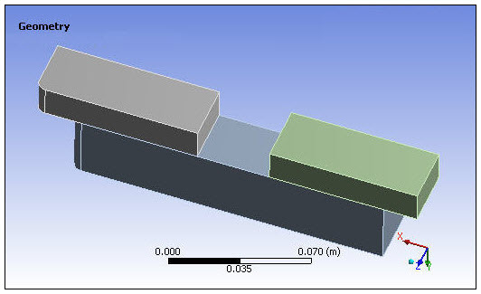
The images below illustrate how contact results are affected by the different scoping types. The model consists of two blocks contacting a third block.
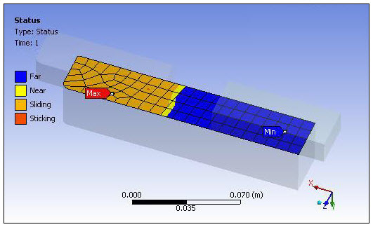
Using the Worksheet method, one Contact Tool was scoped to the contact pair on the left, and another one was scoped to the contact pair on the right. This allows you to view the contact results for each contact pair individually. The contact status for the contact pair on the left is shown below.
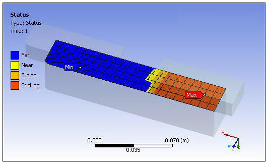
The contact status for the contact pair on the right is shown below.
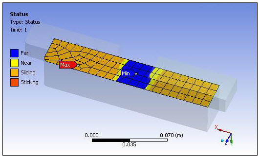
A third Contact Tool scoped to the surface of the large block (using the Geometry Selection method) enables you to view the contact status averaged over that surface, as shown below.
Contact Results Restrictions
Note the following restrictions regarding contact results:
When a contact result is scoped to a face of an assembly, a contact result may not be obtained in certain cases, especially if the scoped face is not a part of any contact region.
Contour contact results are not reported for 3D edge contact.
If you use the option on a Contact Tool contained in the Connections folder, and use the Worksheet to scope these Initial Contact results, the application displays the contour results for the geometry scoping of the contact pairs, not the individual contact elements. Therefore, and as illustrated above by the third Contact Tool scoped to a surface, the results appear as if the scoping is to the geometric faces.
If the contact status of all nodes of a contact element is FAR (or 0), then 16.0 will report all contact results as undefined.
For any contact result, the averaged contact results at 16.0 can display values that differ from values of previous revisions, if:
(a) two contact elements share nodes, and,
(b) one of the elements has a FAR contact status, and,
(c) one of the elements does not have a FAR status.
This is because, prior to 16.0, the elements with FAR status reported values that were ZERO. At 16.0, these elements have no values and are not involved in the averaging process.