The Meshing application provides support for meshing 0-thickness walls, or baffles, as non-manifold faces of a solid body. For such models, you do not have to adjust the mesh size to capture the thin regions.
Characteristics and limitations of baffle meshing include:
For part/body level meshing, baffle meshing is supported by the Patch Conforming Tetra, Patch Independent Tetra, and MultiZone mesh methods only. If you apply any other mesh method to a body containing baffles, the mesh method will be suppressed, and the reason (not supported) will be reported in the Active read-only field in the Details View. In such cases, the body will be meshed with the Patch Conforming Tetra mesh method.
When the MultiZone mesh method is used, the body with a baffle must be meshed with a free mesh of tetrahedral elements. For this reason, you must set the Free Mesh Type to Tetra for bodies with baffles.
The Patch Conforming Tetra and Patch Independent Tetra mesh methods support inflation of baffles. The MultiZone mesh method does not support inflation of baffles.
When the Patch Conforming Tetra mesh method is used, inflation layers will stair step at free boundary edges of the baffles.
When the Patch Independent Tetra mesh method is used and Collision Avoidance is set to Stair Stepping, inflation layers will stair step at free boundary edges of the baffles. However, if Collision Avoidance is set to Layer Compression, full prism columns appear at the free boundary edges.
Program Controlled inflation is supported (that is, if you select Program Controlled inflation, baffles are automatically selected to be inflation boundaries unless they are in a Named Selection).
Only two-sided growth cases for inflation are supported.
Pyramid transitions are supported.
Prism/pyramid elements are not supported for meshing crossed/intersecting baffles.
There is a single set of nodes on the internal face.
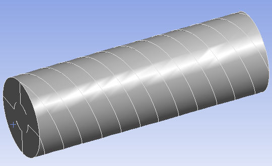
Figure 193: Cylinder Containing Baffles shows a model of a cylinder that contains a series of baffles.
In Figure 194: Section Cut Showing Baffle Meshing, the model was meshed using Program Controlled inflation. Since the baffles were not in a Named Selection, they were automatically selected to be inflation boundaries. A section plane was activated to view a section cut through the model, and the baffle faces were selected in the Geometry window.
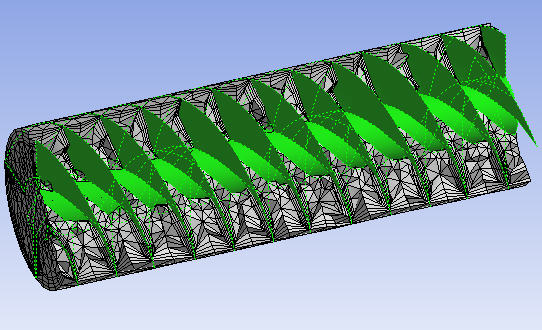
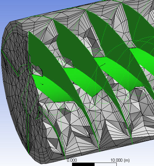
Figure 195: Detail of Inflation on Baffles shows a detailed view of the inflation layers on the baffles.