


When preparing geometry for meshing, it may be advantageous to split an edge into two virtual edges separated by a vertex. For example, in the case of a rectangular face in which a single edge on one side of the face corresponds to two edges on the opposite side, you can split the single edge so that node alignment across the face can have similar spacing. This can be achieved by creating Virtual Split Edge objects. You can also modify the split interactively by dragging the newly created vertex along the length of the original edge. This alters the split location.
Splitting an Edge
Insert a Virtual Topology object in the tree.
Choose the edge selection filter (Ctrl+E) and then in the Geometry window, pick the edge that you want to split. The selected edge can be either a "real" edge or a previously-defined virtual edge.
Note: To simplify specification of the split location, when picking the edge to split you should position your cursor at the point on the edge where you want the split to occur. Then select Virtual Split Edge at + as described in step 3.
Create the Virtual Split Edge using either of these methods:
To define the split location according to your cursor location on the edge, right-click in the Geometry window and select from the context menu, or choose Split Edge at + on the Virtual Topology context toolbar.
To define the split without specifying the location, select the edge you want to split, right-click in the Geometry window, and select from the context menu, or choose Split Edge on the Virtual Topology context toolbar. By default the split ratio will be set to 0.5, but you can change it later by using the Virtual Topology Properties dialog.
Note: If the software cannot create the split, the error message “Unable to split the edge at selected location or with given split ratio” will appear and the split will not be created.
In step 3, if you created the Virtual Split Edge object by selecting Virtual Split Edge at +, the split ratio is determined automatically by the software. If you created it by selecting Virtual Split Edge, you can either accept the default of 0.5 or specify a different split ratio by right-clicking and selecting Edit Selected Virtual Entity Properties.... Then edit the Split Ratio field on the Virtual Topology Properties dialog.
The split ratio defines the location of the split by specifying the ratio between the distance from the start point of the edge to the split location and the overall length of the edge. Specify a value from 0 to 1. For example, a value of 0.5 will split the edge into two edges of equal length. A value of 0.75 will split the edge into two edges where the first edge is three quarters of the length of the original edge, and the second edge is only one quarter of the length of the original edge. A value of 0 or 1 is valid only if the selected edge is a closed edge. In the case of a closed edge, such as a circle, the edge will be split into two edges, and the new vertex will be placed along one of the new edges.
You can change the location of the split at any time by accessing the Virtual Topology Properties dialog and editing the Split Ratio field, or by modifying the edge split interactively.
To modify an edge split interactively, select any portion of the original edge or its vertex split location in the Geometry view. Then, while pressing F4 on the keyboard, drag the mouse along the length of the edge to redistribute the split ratio. The display indicates the initial 3-D location of the split, together with a preview of its new location and split ratio.
When you change the split ratio of an edge split that is attached to a face split, both the edge split and the face split are adjusted accordingly.
Virtual Split Edge Dependency
Existing virtual edges and/or existing virtual split edges can be used to create new virtual split edges. Within the split edge hierarchy, a virtual split edge depends on a virtual edge if the latter is used to create the former. Similarly, a virtual split edge depends on another virtual split edge if the latter is used to create the former.
Note: If a virtual edge was created from a virtual split edge, you cannot delete the virtual split edge without first deleting the virtual edge. Conversely, if a virtual split edge was created from a virtual edge, you cannot delete the virtual edge without first deleting the virtual split edge.
A warning message appears in the Messages window for each failed deletion. To highlight the geometry that is responsible for a message, select the message, right-click, and select Show Problematic Geometry from the context menu.
Locking Locations of Dependent Virtual Split Edges
In cases involving virtual split edge dependency, you can choose whether the locations of dependent splits are locked or unlocked when the location of the parent split is modified. If unlocked, the location of the dependent split moves to maintain its defined split ratio when the parent is modified. If locked, the location of the dependent split persists when the parent is modified. Regardless of the setting, the location of the dependent split will move if preserving its location would invalidate the split (see Figure 227: Overridden Locked Dependent Splits for an example).
Note: For parametric updates, all virtual split edges are treated as unlocked.
Highlight the Virtual Topology object in the tree.
Note: Locking must be set globally on the Virtual Topology object. It cannot be set locally for individual Virtual Split Edge objects.
In the Details View, set the Lock position of dependent edge splits option to Yes (default) or No.
The following figures illustrate locking. Figure 224: Original Virtual Split Edge with Dependent Virtual Split Edge shows an example in which a split at .5 was defined on original edge ab, creating two new edges—ac and cb. A second split at .5 was then defined on edge cb, creating two new edges—cd and db.
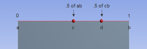
Figure 225: Unlocked Dependent Splits shows the expected behavior when Lock position of dependent edge splits is set to No, and the split located at point c is changed from .5 to .1. Notice that point d has moved to maintain its defined split ratio at .5 of cb.
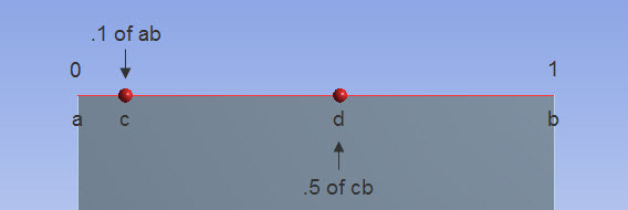
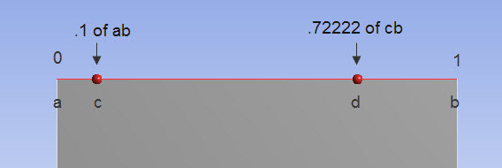
Figure 226: Locked Dependent Splits shows the expected behavior when Lock position of dependent edge splits is set to Yes, and the split located at point c is changed from .5 to .1. Notice that in this case point d has not moved, and the split ratio is now .72222 of cb.
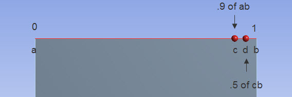
In Figure 227: Overridden Locked Dependent Splits, the split located at point c was changed from .5 to .9. Even with locking set to Yes, in this case point d was moved because preserving its location would have invalidated the split (that is, if its original location had been preserved, point d would no longer be located on edge cb).
Notes on Virtual Split Edges
When the Sweep mesh method is used, the guiding edges must have consistent lengths to obtain a regular mesh in the sweep direction. You can define virtual split edges to achieve consistent lengths for these edges.
If your Geometry view is configured to display , you can conveniently review virtual split edges by clicking the Virtual Topology group in the Tree Outline. In this mode, split edges will be highlighted in two different colors (automatically assigned) to draw attention to the splits.
You cannot use the virtual split edge feature to split edges belonging to line bodies.