


Blocking Display
When blocking is created, the blocking vertices, edges, and faces are associated with the closest geometry points, curves, and faces. Color coding is used to indicate how block edges and vertices are associated to the geometry, which can constrain the movement of the blocking edges and vertices. See Associating the blocking to geometry.
- Red vertices are associated to points on the geometry. If you attempt to move these without first disassociating, the geometry may also be modified.
- Green vertices and edges are associated to curves on the geometry. You may move the vertices but they will be constrained to stay on the associated curve.
- Purple (pink) vertices and edges are associated to surfaces. You may move the vertices, but they will be constrained to stay on the associated body.
- Blue (cyan) vertices and edges are internal and not associated to any geometry. You may move the vertices freely.
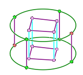
The Mesh Display panel includes controls to show the Connectivity of blocking edges and faces. If enabled, edge color indicates the number of connected faces.
- Red = one face, as in a perimeter edge for surface blocking.
- Blue = two faces.
- Pink = three faces.
- Yellow = interior edges in volume blocking, connected to more than three faces.
Note:
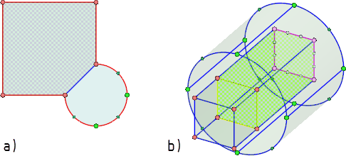
Similarly, if enabled, Faces are colored if shared by two volume blocks.
The Mesh Display panel also includes a control to indicate the type of block face by the presence of a checkerboard pattern.
- Patterned faces indicate mapped.
- Solid color faces indicate free.
For a full description, see Setting mesh display options.