The procedure for defining the remeshing method is as follows:
In the sub-task menu, select the Global remeshing menu item.
 Global remeshing
Specify the region where the first (or only) remeshing is to be performed. (See Local Remeshing for information about defining multiple remeshing regions.)
1-st local remeshing
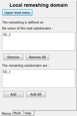
In the Local remeshing domain panel (Figure 16.10: The Local remeshing domain Panel), follow the appropriate steps below:
If the subdomain or subdomains in the top list completely define the region where the remeshing is to be performed, simply click Upper level menu at the top of the panel.
If the top list does not contain the correct subdomain(s), follow these steps:
If there is a subdomain in the top list that is not a part of the region where the remeshing is to be performed, select it and click Remove. It will be moved from the top list to the bottom list, indicating that it will not be remeshed.
If a subdomain that should be part of the remeshing region is not in the top list, select it in the bottom list and click Add. It will be moved from the bottom list to the top list, indicating that it will be remeshed.
When the top list contains the correct subdomain(s), click Upper level menu at the top of the panel.
Select the remeshing method to be used, and set the relevant parameters. See Choosing a Remeshing Technique for guidelines on choosing the remeshing method.
The inputs for the Thompson transformation (described in Thompson Transformation) are as follows:
Select the Thompson Transformation menu item.
Thompson Transformation
For each boundary (including each intersection with an adjacent subdomain), specify the imposed value for one of the
 components.
 Select the boundary or adjacent subdomain in the Condition on Global Field panel.
Click Modify.
Select the appropriate component of the
 vector (first, second, or (in 3D)
third), and enter the New value for
the selected component when prompted. See Example for more information.
vector (first, second, or (in 3D)
third), and enter the New value for
the selected component when prompted. See Example for more information.Repeat for each boundary or adjacent subdomain.
Click Upper level menu at the top of the panel when you are done.
The inputs for the method of spines (described in Method of Spines) are as follows:
Select the Method of Spines menu item.
Method of Spines
Specify the inlet for the system of spines (that is, the initial spine for the remeshing domain) by selecting the intersection with the appropriate boundary set or subdomain and clicking Confirm.
Specify the outlet for the system of spines (that is, the final spine for the remeshing domain) by selecting the intersection with the appropriate boundary set or subdomain and clicking Confirm.
The method of spines is not available in 3D.
The input for the Euclidean distance method (described in Euclidean Method) is as follows:
Select the Euclidean Method menu item.
Euclidean Method
The inputs for the method of planes (described in Method of Planes) are as follows:
Select the Method of Planes menu item.
Method of Planes
Specify the inlet for the system of planes (that is, the initial plane for the remeshing domain) by selecting the intersection with the appropriate boundary set or subdomain and clicking Confirm.
Specify the outlet for the system of planes (that is, the final plane for the remeshing domain) by selecting the intersection with the appropriate boundary set or subdomain and clicking Confirm.
The inputs for the thin shell method (described in Thin Shell Method) are as follows:
Select the Thin Shell Method menu item.
Thin Shell Method
Specify the master moving surface (commonly the boundary set that comes into contact with the mold) by selecting the intersection with the appropriate boundary set or subdomain and clicking Confirm.
When there are several sub-tasks, one for each layer of the parison, the master surface must be defined only once. If the master surface has been specified previously (that is, in another sub-task), you will just confirm it in this step.
Important: For multilayer applications, you must be sure to use the thin shell remeshing rule for all layers (that is, in the sub-task for each layer).
The inputs for Optimesh (described in Optimesh) in 2D are as follows:
Select the Optimesh-2D menu item.
Optimesh-2D
For each boundary (including each intersection with an adjacent subdomain), specify the imposed value for one of the
 components.
 Select the boundary or adjacent subdomain in the Condition on Global Field panel.
Click Modify.
Select the appropriate component of the
 vector (first or second), and enter
the New value for the selected
component when prompted. See Example for more information.
vector (first or second), and enter
the New value for the selected
component when prompted. See Example for more information.Repeat for each boundary or adjacent subdomain.
Click Upper level menu at the top of the panel when you are done.
The inputs for Optimesh (described in Optimesh) in 3D are as follows:
Select the Optimesh-3D menu item.
Optimesh-3D
Specify the inlet for the system of planes (that is, the initial plane for the region to be sliced, described in Euclidean Method for the Euclidean method) by selecting the intersection with the appropriate boundary set or subdomain and clicking Confirm.
Important: Recall that the slices must be perpendicular to the extrusion axis. Ansys Polydata will check the inlet and outlet of the system of planes; they must be real planes and they must be perpendicular to the extrusion axis (
 ,
,  , or
, or  direction).
Specify the outlet for the system of planes (that is, the final plane for the region to be sliced, described in Euclidean Method for the Euclidean method) by selecting the intersection with the appropriate boundary set or subdomain and clicking Confirm.
Important: Note that the line kinematic condition is recommended when Optimesh is used. See Discontinuity of the Normal Direction and Guidelines for 3D Extrusion Problems for details.
The input for the Lagrangian method (described in Lagrangian Method) is as follows:
Select the Lagrangian menu item.
Lagrangian
The inputs for the thin shell method with Lagrangian master (described in Thin Shell Method with Lagrangian Master) are as follows:
Select the Thin Shell Method+Lagrangian master menu item.
Thin Shell Method + Lagrangian master
Specify the master moving surface (commonly the boundary set that comes into contact with the mold) by selecting the intersection with the appropriate boundary set or subdomain and clicking Confirm.
The input for the Lagrangian method on the border only (described in Lagrangian Method on Borders) is as follows:
Select the Lagrangian on the border only menu item.
Lagrangian on the border only
The inputs for the streamwise method (described in Section Streamwise Method) are as follows:
Select the Streamwise Method menu item.
Streamwise Method
Specify the inlet for the system of planes (that is, the initial plane for the remeshing domain) by selecting the intersection with the appropriate boundary set or subdomain and clicking Confirm.
Specify the outlet for the system of planes (that is, the final plane for the remeshing domain) by selecting the intersection with the appropriate boundary set or subdomain and clicking Confirm.
The inputs for the elastic method (described in Elastic Methods) are as follows:
Select the Elastic remeshing menu item.
Elastic remeshing
For each non-free-surface boundary (including each intersection with an adjacent subdomain), specify the type of constraints you want to impose.
Select the boundary or adjacent subdomain in the Condition on displacement along borders panel.
Click Modify.
To allow the points on the border to move along the tangent to the border, select No NORMAL displacement (the default condition). To fix the points so that they do not move in the normal or tangential direction along the border, select No displacement.
The default condition (No NORMAL displacement) allows for more degrees of freedom, and therefore produces smoother remeshing, but it can lead to a change in the geometry of a border that contains corners. The No displacement option is therefore recommended for borders that contain corners.
Repeat for each boundary or adjacent subdomain.
Click Upper level menu at the top of the panel when you are done.
The inputs for the improved elastic method (described in Elastic Methods) are as follows:
Select the Improved Elastic remeshing menu item.
Improved Elastic remeshing
Specify whether the remeshing is defined on a free jet and whether you intend to stabilize the free jet by clicking either Yes or No.
Important: In order to click Yes, you should verify that the remeshing domain is sliceable. Ansys Polydata performs a check related to the sliceability of the mesh, and will present a message if the mesh is not sliceable. Furthermore, you should verify that the remeshing domain and constraint of the free jet is defined appropriately. If the remeshing domain includes the free jet and the die domains, then the constraint of the free jet should be defined such that the starting coordinates for the portion of the remeshing domain where the constraint is applied is after the die end. See Constraint on Global Displacement for more details.
If you clicked Yes, perform the following:
Specify the inlet for the system of planes (that is, the initial plane for the remeshing domain) by selecting the intersection with the appropriate boundary set or subdomain and clicking Confirm.
Specify the outlet for the system of planes (that is, the final plane for the remeshing domain) by selecting the intersection with the appropriate boundary set or subdomain and clicking Confirm.
For each non-free-surface boundary (including each intersection with an adjacent subdomain), specify the type of constraints you want to impose.
Select the boundary or adjacent subdomain in the Condition on displacement along borders panel.
Click Modify.
To allow the points on the border to move along the tangent to the border, select No NORMAL displacement (the default condition). To fix the points so that they do not move in the normal or tangential direction along the border, select No displacement.
The default condition (No NORMAL displacement) allows for more degrees of freedom, and therefore produces smoother remeshing, but it can lead to a change in the geometry of a border that contains corners. The No displacement option is therefore recommended for borders that contain corners.
Repeat for each boundary or adjacent subdomain.
Click Upper level menu at the top of the panel when you are done.
Modify the element distortion check information, if necessary. After completing the inputs for your selected remeshing method, Ansys Polydata will bring you to the Element distortion check menu, where you can make changes to the criteria Ansys Polyflow will use to check for element distortion as a result of the remeshing. The default settings are appropriate for most cases, so you can generally select Accept the current setup without making any changes.
If any of the distortion limits is met during an evolution or time-dependent simulation, Ansys Polyflow will stop the calculation or simply warn you, depending on what you have specified in this menu.
When using Stop if distortion limit exceeded mode, the calculation of the current time step is stopped and restarted with a time step divided by 2. This option is to be used combined with Adaptive Meshing Technique (see User Inputs for Adaptive Meshing for frequency of the meshing).
When using Dt reduced + Stop if distortion limit exceeded, the current step is rejected if the element quality no longer matches one of the criteria. The time step will be reduced according to the specified reduction rate, while adaptive meshing may be anticipated by skipping time steps.
For 2D and 3D transient cases with moving boundaries, without entry and exit, and where the Lagrangian remeshing technique is invoked, the element distortion check is activated by default with the option of time step reduction.