


3D extrusion problems require special attention along corner lines, which originate from sharp angles in the die lip section. Along these corners, the normal is actually discontinuous at the level of mesh discretization.
Ansys Polyflow provides two techniques to solve this difficulty: separating the sheets of the free surface into several boundary sets, located between corner lines; or using the line kinematic condition, which does not require division into multiple boundary sets. The multiple-boundary-set method is referred to as the surface kinematic condition. Note that the line kinematic condition is not the default method, but it is recommended for complex profile extrusion.
Given that discontinuous slopes between finite elements will always occur for a nonplanar, free surface, the concept of a corner line may not be immediately clear. In fact, a corner exists when slope discontinuities do not disappear when the element size approaches zero (that is, when the mesh is refined).
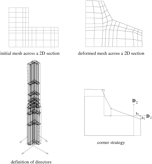
For the surface kinematic condition, it is convenient to consider two boundary
sets. In this case, there will be two directors  , two geometrical degrees of freedom
  , and two kinematic conditions associated with each node of a
corner line, because the node belongs to two boundary sets on which separate
free-surface conditions are defined. Therefore, these special nodes have the
freedom to move in a plane orthogonal to the main direction of extrusion. Figure 15.4: Definition of a Separate Boundary Set for Each Sheet of the Free Surface
(Surface Kinematic Condition) shows an example
for the surface kinematic condition.
, and two kinematic conditions associated with each node of a
corner line, because the node belongs to two boundary sets on which separate
free-surface conditions are defined. Therefore, these special nodes have the
freedom to move in a plane orthogonal to the main direction of extrusion. Figure 15.4: Definition of a Separate Boundary Set for Each Sheet of the Free Surface
(Surface Kinematic Condition) shows an example
for the surface kinematic condition.
Figure 15.4: Definition of a Separate Boundary Set for Each Sheet of the Free Surface (Surface Kinematic Condition)
When this method is used, it is important for the mesh to have a sufficient number of boundary sets to allow for proper piecewise definition of the free surface around edges.
For the line kinematic condition, the kinematic condition is written differently than in Equation 15–14 or Equation 15–15. Rather than requiring a zero velocity normal to the free surface, the velocity vector is required to be tangent to a series of lines included in the surface and starting from the die lip section. These lines generate the free surface.
This condition is stronger than the standard kinematic condition, because it allows each nodal position to be relocated in a plane normal to the direction of extrusion (that is, in two directions rather than one). Because each point (rather than just the corner points, as in the multiple-boundary-set method) is relocated in two directions, there is no need to define multiple boundary sets (although it is possible to do so without affecting the solution). The number of position variables is slightly higher with the line kinematic condition than with the surface kinematic condition.
The line kinematic condition is the recommended numerical scheme for complex profile extrusion (direct or inverse), and it can only be used with the Optimesh, streamwise, or improved elastic remeshing techniques described in Remeshing.