


For steady-state extrusion simulations that do not involve any implicit constraints on the extrudate (for example, plane of symmetry, slip conditions, or guiding devices), Ansys Polyflow will apply a global displacement constraint if the problem satisfies certain conditions, which are described later in this section.
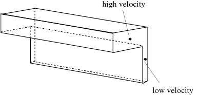
To avoid excessive global displacement, the model allows the addition of a force and a torque on the free jet (or a portion of it). The computed force and torque can be interpreted as those produced by a guide used to prevent deviations in the extrudate shape. In a well-balanced die, the deviation of the extrudate is small and the force and torque are also small. An unbalanced die, however, will have very large deviations. Consider the unbalanced die illustrated in Figure 15.21: Flow Through an Unbalanced Die.
The extrusion of such a profile leads, in general, to a large deviation in the extrudate due to the differences in velocity. The deviation of the jet is produced by a nonzero average transverse velocity (ATV) in the cross-section (for example, at the die exit).
To avoid large displacements (translation and rotation) of the free jet, Ansys Polyflow applies a force and a torque on all or part of the extrudate, if the problem satisfies certain conditions described later in this section.
The force  acts like a body force in the equation of motion, while the torque
 acts like a distributed torque by use of an asymmetric stress
tensor in the equation of motion. The values of the force and torque components are
computed by Ansys Polyflow precisely so as to obtain a zero averaged transverse
velocity (or rotation). When the large displacements are avoided, convergence of the
solution becomes much easier.
acts like a distributed torque by use of an asymmetric stress
tensor in the equation of motion. The values of the force and torque components are
computed by Ansys Polyflow precisely so as to obtain a zero averaged transverse
velocity (or rotation). When the large displacements are avoided, convergence of the
solution becomes much easier.
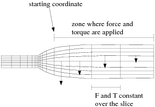
The mesh is sliced according to the definition of the remeshing rule. On each node slice (that is, group of all nodes belonging to the same slice), the force and torque are assumed to be constant, as shown in Figure 15.22: Sliced Domain with Force and Torque.
Furthermore, the component of the force in the flow direction and the component of the torque in the transverse direction have imposed values of zero. Since the force and torque are constant in each slice, their effect on the shape of the extrudate section is small.
The following limitations apply to the constraint on global displacement:
It is available only for non-axisymmetric extrusion problems. (Axisymmetry is a global displacement constraint in itself.)
The extrusion direction must be aligned with the
 ,
,  , or
, or  direction. When Optimesh 3D or streamwise remeshing is
used, Ansys Polydata will check that the inlet and outlet of the system
of planes are real planes and are perpendicular to the
direction. When Optimesh 3D or streamwise remeshing is
used, Ansys Polydata will check that the inlet and outlet of the system
of planes are real planes and are perpendicular to the  ,
,  , or
, or  direction.
 Optimesh, the streamwise method, the method of spines (2D), or the Euclidean method (3D) must be used as the remeshing method, so that slicing is available; the Thompson transformation cannot be used.
Although improved elastic remeshing does not require a sliceable mesh, the constraint on the free jet requires such a mesh. Hence, you will be able to apply the constraint on the free jet coupling when using this remeshing technique, if the mesh is at least sliceable. If the mesh is not sliceable on the extrudate, Ansys Polydata will not warn you, but Ansys Polyflow will stop on an error message.
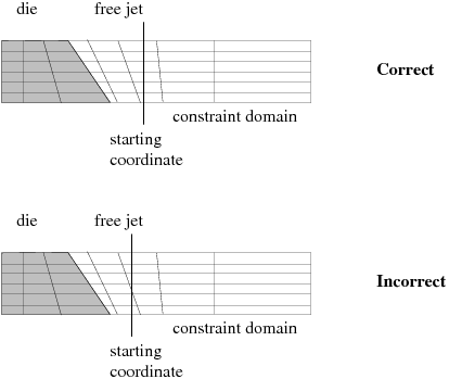
The plane passing by the starting point and perpendicular to the extrusion direction must not cross any slice (that is, the force or torque must either apply on an entire slice or not apply at all on the slice). If this condition is violated, the solver will not converge. Figure 15.23: Constraint on the Starting Coordinate illustrates correct and incorrect positions for the starting coordinate.
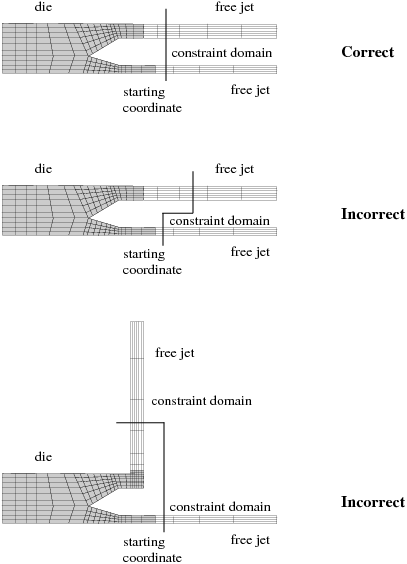
For multiple-jet simulations, the extrusion direction must be the same for all jets. The force and torque on each jet will, however, be computed separately. Figure 15.24: Constraint on Multiple-Jet Problems illustrates multiple-jet problems for which the constraint can and cannot be applied.
The constraint on global displacement is not compatible with velocity boundary
conditions on the extrudate (for example, plane of symmetry:  ; belt conveyor:
  ,
,  ). These velocity conditions are sufficient to avoid global
displacements, so no additional constraints are required. For this reason, some
force or torque components can be set to zero. Table 15.1: Force and Torque Components for Geometries and Boundary
Conditions identifies
the force and torque components for different cases as computed (C), equal to
zero (0), or not computed (N) because they are incompatible with the boundary
conditions. In this table, the flow direction is
). These velocity conditions are sufficient to avoid global
displacements, so no additional constraints are required. For this reason, some
force or torque components can be set to zero. Table 15.1: Force and Torque Components for Geometries and Boundary
Conditions identifies
the force and torque components for different cases as computed (C), equal to
zero (0), or not computed (N) because they are incompatible with the boundary
conditions. In this table, the flow direction is  for non-axisymmetric 2D geometries, and
  for axisymmetric and 3D geometries.
The table tells you which component of the force or torque will be non-zero when the global displacement constraint is used. If you specify an inconsistent constraint, Ansys Polydata will warn you. Ansys Polydata cannot tell you when you might benefit from a global displacement constraint.
Table 15.1: Force and Torque Components for Geometries and Boundary Conditions
| Geometry | Boundary Conditions |

|

|

|

|

|

|
|---|---|---|---|---|---|---|---|
| 2D axisym (Figure 15.25: 2D Geometries a) | line of axisymmetry | N | – | 0 | – | – | – |
| 2D planar (Figure 15.25: 2D Geometries b) | no plane of symmetry | C | 0 | – | – | – | – |
| 2D planar (Figure 15.25: 2D Geometries c) | plane of symmetry, 
| N | 0 | – | – | – | – |
| 2D planar (Figure 15.25: 2D Geometries d) |
 , , 
| N | – | – | – | – | – |
| 3D (Figure 15.26: 3D Geometries a) | no plane of symmetry | C | C | 0 | 0 | 0 | C |
| 3D (Figure 15.26: 3D Geometries b) | one plane of symmetry, 
| C | 0 | 0 | 0 | 0 | 0 |
| 3D (Figure 15.26: 3D Geometries c) | two planes of symmetry,  or or 
| 0 | 0 | 0 | 0 | 0 | 0 |
This information must come either from your knowledge of the process being modeled or from your observation of large deviations in a previous simulation.
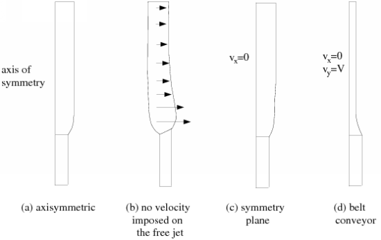
For 2D geometries, there is no torque and
 or
or  is zero. Axisymmetric geometries (Figure 15.25: 2D Geometries a) are incompatible with the constraint on
global displacement.
is zero. Axisymmetric geometries (Figure 15.25: 2D Geometries a) are incompatible with the constraint on
global displacement. For a 2D geometry without velocity boundary conditions on the free jet (Figure 15.25: 2D Geometries b), there is only one component of force that is computed. 2D geometries with a symmetry plane (Figure 15.25: 2D Geometries c) or with normal (to the extrusion axis) velocity imposed (Figure 15.25: 2D Geometries d) are incompatible with the constraint on global displacement.
For 3D geometries without velocity boundary conditions on the free jet (Figure 15.26: 3D Geometries a), the transverse components of the force are computed in order to avoid the displacement in the transverse direction, and the force component in the flow direction is equal to zero; the torque components in the flow direction is computed in order to avoid extrudate rotation, and the other torque components are equal to zero.
For 3D geometries with one plane of symmetry (Figure 15.26: 3D Geometries b), extrudate rotation is not possible, so the torque is not taken into account. Since displacement in the direction perpendicular to the symmetry plane is not allowed, the force in this direction is imposed to be zero.
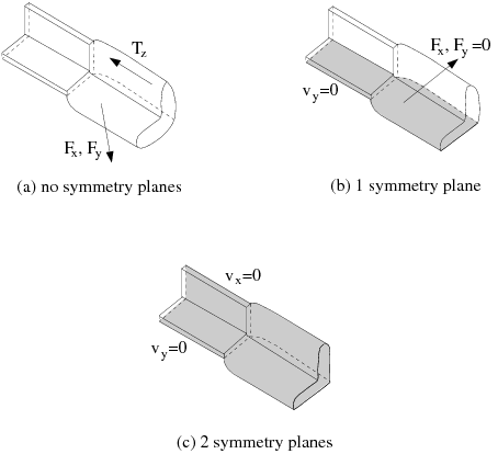
For a 3D geometry with two planes of symmetry or other velocity boundary conditions (Figure 15.26: 3D Geometries c), the transverse and rotation displacements of the free jet are not possible, so the force and torque are not taken into account.
Ansys Polydata detects these situations automatically and sets the appropriate force and torque components to zero. If you try to use the constraint on global displacement when it is incompatible with the boundary condition, Ansys Polydata will inform you of the incompatibility in an error message.
For steady-state extrusion simulations that do not involve any explicit constraints on the extrudate (for example, plane of symmetry or full slip conditions), the constraint on global displacement is recommended, and Ansys Polydata will enable it automatically. As a part of this constraint Ansys Polydata will also automatically generate force and torque fields for the extrudate, labeled F_extrusion and M_extrusion, respectively.
If you disable it, poor convergence or even divergence may occur, typically with a large-amplitude displacement of the free surface or moving interface for intermediate converged steps when evolution on moving boundaries is used.
If you want to modify the constraint on the global displacement of the free jet, the procedure is as follows:
Set up the extrusion problem as usual, following the steps in General Procedure.
Enter the menu for the constraint on global displacement (in the task menu).
 Constraint on free jet displacement
The option is already turned on. To turn it off, select Disable constraint on displacement.
Modify the application of the constraint on all or part of the remeshing domain.
Options
By default, Ansys Polydata will compute the extrusion direction and apply the appropriate force and torque on all remeshing domains. This is indicated by the default selection of the Constraint on all the remeshing domain option.
Constraint on all the remeshing domain
To apply the constraint to only a portion of the remeshing domain, select Constraint on a part of the remeshing domain and follow the steps below:
Constraint on a part of the remeshing
domain
Here, the algorithm stabilizes the extrudate along the actual extrusion direction. In other words, if the extrudate moves towards positive values of the coordinate along the extrusion direction, Ansys Polydata informs you that
Forces applied on [starting coord;
+inf]
This indicates that the constraint should be applied to the portion of the remeshing domain where the coordinate in the extrusion direction is greater than the starting coordinate:
If the extrudate moves towards negative values of the coordinate along the extrusion direction, Ansys Polydata informs you that
Forces applied on [-inf; starting
coord]
This indicates that the constraint should be applied to the portion of the remeshing domain where the coordinate in the extrusion direction is smaller than the starting coordinate.
Specify the starting coordinate for the portion of the remeshing domain where the constraint should be applied.
Modify starting coordinate
The coordinate will be in the direction of extrusion.