An interior angle is defined as the angle between two adjacent edges at a vertex. For example, the interior angles of a square are of 90 degrees, while the angles of an equilateral triangle are of 60 degrees. By default, the minimum and maximum angles are set to 5 and 170 degrees, respectively.
The aspect ratio of an element is defined as the ratio of the lengths of the longest edge to that of the shortest edge. By default, a maximum aspect ratio of 10 is set.
The bend is evaluated based on the cross product between unit normal directions
 and
and  defined at two opposite vertices of a quadrilateral defined in the
plane or in the space. More precisely, it is defined as
defined at two opposite vertices of a quadrilateral defined in the
plane or in the space. More precisely, it is defined as  . Obviously for a triangular face, the bend is always zero and
consequently a tetrahedron is never bent. A regular quadrilateral face has also a
zero bend; however, the bend of a quadrilateral in the space may equal 1 or 2 when
an edge is rotated by 90 or 180 degrees out of the plane of the quadrilateral,
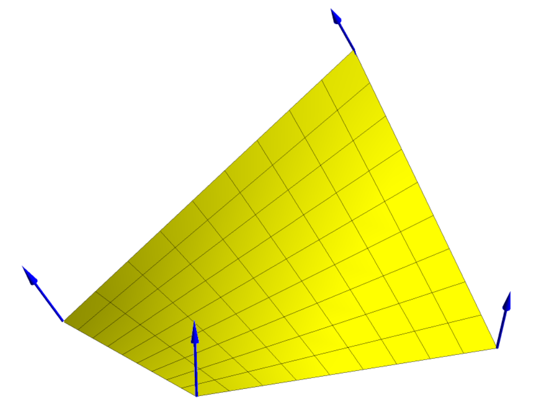
respectively. The element displayed in Figure 16.11: Bent Quadrilateral and Unit Normal Directions at Vertices is obtained by lifting one vertex of a square element in the upward direction
over a distance that corresponds to 70% of the side length; it exhibits a bend of
0.33. If that same vertex was placed above the diagonally opposite one, at a
distance corresponding to the side length, the bend would have been of 1.58. By
default, a maximum bend of 0.8 is set.
. Obviously for a triangular face, the bend is always zero and
consequently a tetrahedron is never bent. A regular quadrilateral face has also a
zero bend; however, the bend of a quadrilateral in the space may equal 1 or 2 when
an edge is rotated by 90 or 180 degrees out of the plane of the quadrilateral,
respectively. The element displayed in Figure 16.11: Bent Quadrilateral and Unit Normal Directions at Vertices is obtained by lifting one vertex of a square element in the upward direction
over a distance that corresponds to 70% of the side length; it exhibits a bend of
0.33. If that same vertex was placed above the diagonally opposite one, at a
distance corresponding to the side length, the bend would have been of 1.58. By
default, a maximum bend of 0.8 is set.
For evaluating the skewness of an element, the transformation that relates the
element  considered in the
  -space and a parent element
  in the
  -space is invoked. Let J denote the Jacobian
of the transformation. The skewness can be evaluated as follows:
-space is invoked. Let J denote the Jacobian
of the transformation. The skewness can be evaluated as follows:
 | (16–19) |
If the transformation is regular, or if J does not vanish, the previous equation is equivalent to
 | (16–20) |
where  and
and  are the volume of the element
  in the
  -space and of the corresponding parent element
  in the
  -space, respectively. The skewness of a triangle and of a
tetrahedron always vanishes.
-space, respectively. The skewness of a triangle and of a
tetrahedron always vanishes.
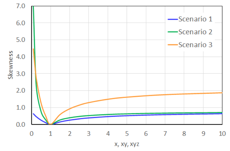
For illustrating the skewness of a deformed hexahedron, consider three deformation scenarios applied to the initially cubic element displayed in Figure 16.12: Three Deformation Scenarios. Note that these three deformation scenarios are applied to an initially cubic element for evaluating the skewness.
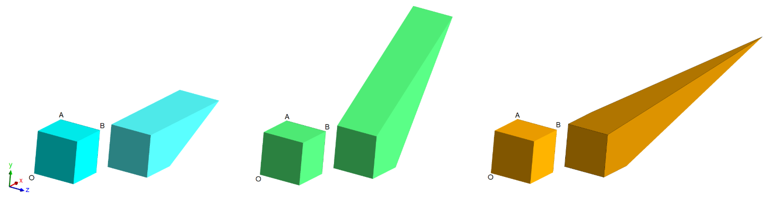
In the first scenario, the segment AB is moved along the x-direction; in the second scenario, the segment AB is moved along the 0xy-bisector; in the third scenario, vertex B moves along the central line of the 0xyz-trihedron. The first two scenarios also apply to a square. Figure 16.13: Skewness Values vs. Element Shape displays the skewness values as a function of the element shape dictated by the segment AB according to the selected scenario of Figure 16.12: Three Deformation Scenarios.