


Evaluates the quality of mapping across source and target meshes. It provides quantitative measures that help identify regions on the target where the mapping failed to provide an accurate estimate of the source data. You can add validation objects under the Imported Element Orientation, Imported Load, Imported Thickness, or Imported Trace objects.
 |
Object Properties
The Details view properties for this object include the following.
| Category | Properties/Options/Descriptions |
|---|---|
|
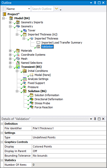
Definition | File Identifier: Specify the file identifier(s) from parent
object. This property is only available when data is imported through the External Data system.
Layer (Imported Trace only): Specify the layer from the PCB layout. Row: The row of the parent worksheet. Data: The data type for the imported load. Component: The vector component (X, Y, Z). Complex Component: The real/imaginary component for complex loads. Shell Face: Specify the top/bottom for loads applied to shells. |
|
Settings | Type: Specify Reverse Validation,
Distance Based Average Comparison, Source
Value, or Undefined Points. Note: Not all options are available when validating Imported Trace or Imported Heat Generation. Number of Points: Available when Distance Based Average Comparison is selected. Specifies how many points to use in the distance based average mapping calculations. Output Type: Specify either Relative Difference or Absolute Difference. (This is not displayed for the Source Value or Undefined Points types.) |
|
Graphics Controls |
Display: Specify either Scaled Spheres, Colored Spheres, Colored Points, Contours, or Isolines (Isolines are only available for Source Value Output Type when element mesh data is provided) Line Thickness: Available when Display is set to Isolines. Control the thickness of the isolines by selecting Single, Double, or Triple. Scale: Specify scale multiplier for increasing and decreasing sphere sizes. Not displayed for Colored Points. Display Minimum: Appears if object state is solved. Graphics display will use this value to show only items above this threshold. Must be greater than the Minimum and less than the Maximum property. (This is not displayed for the Undefined Points type.) Display Maximum: Appears if object state is solved. Graphics display will use this value to only show items below this threshold. Must be greater than Minimum and less than Maximum property. (This is not displayed for the Undefined Points type.) Display In Parent: Graphics items can be overlaid on parent objects when this item is set to On. Legend Divisions: Control how many contour colors to use in displaying graphics data. (This is not displayed for the Undefined Points type.) |
|
Statistics |
Minimum: Read-only minimum value for entire mapped points. (This is not displayed for the Undefined Points type.) Maximum: Read-only maximum value for entire mapped points. (This is not displayed for the Undefined Points type.) Number Of Items: Read-only number of currently displayed items |
Tree Dependencies
Valid Parent Tree Objects: Imported Element Orientation, Various Imported Load Types, Imported Thickness, or Imported Trace objects.
Insertion Methods
Select the imported object and:
Select the Validation option on the Imported Fields Context tab.
Right-click and select > .
Right-click Options
In addition to common right-click options, relevant right-click options for this object include:
: Executes the validation.
: Exports the data to a text file in tabbed delimited format.
API Reference
See the Mapping Validation section of the ACT API Reference Guide for specific scripting information.
Additional Related Information
Imported Load Object Reference
Imported Thickness Object Reference