Imported Trace

Manages the complexities of Printed Circuit Boards (PCBs), significantly reducing the time needed to generate a geometry and mesh.

Object Properties

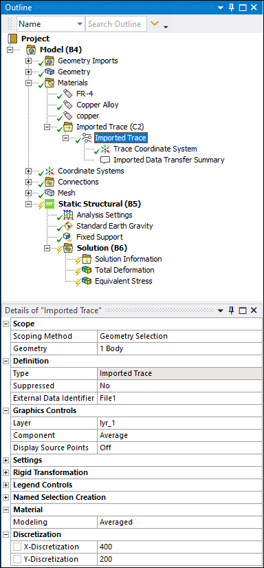
The Details pane for the Imported Trace object includes the following properties.

CategoryProperties/Options/Descriptions

Scope

Scoping Method

Specify as Geometry Selection (default) or Named Selection.

Geometry

Displayed when the Scoping Method is set to Geometry Selection (default). Displays the type of geometry and the number of bodies to which the object has been applied using the selection tools. Use the selection filter to pick geometry, click in the Geometry field, then click Apply.

Named Selection

Displays when the Scoping Method is set to Named Selection. This field provides a drop-down list of available user-defined Named Selections.

Definition

Type

A read-only property that describes the object : Imported Trace.

Suppressed

Suppress the object as desired (Yes/No).

External Data Identifier

Once you have imported data from Workbench using an External Data, this property provides a drop-down list of available ECAD files from the files specified in the external system. Once you import External Data directly into Mechanical, this property displays a unique identifier for the external file, such as File1.

Shell Offset (Shells Only)

Set the desired shell offset.

Graphics Controls

Layer

This property is available for Surface bodies only. It enables you to view the metal fraction data from that layer on the mesh.

Component

Options include Average (default), X Component, Z Component, and Z Component.

Display Source Points

Toggle display of source point data. Options include Off (default) and On.

Settings

Mapping Control

Options include Program Controlled (default) and Manual. See the Data Transfer Mesh Mapping section for additional information.

Mapping

A read-only property that describes the setting - Profile Preserving

Weighting

A read-only property that describes the setting - Shape Function

Interpolation

Options include Nondirectional (default) and Directional. The Nondirectional option calculates effective conductivity by averaging the trace data in each element. Using the Directional option, the application calculates the effective orthotropic conductivity for each element using the position and values of the trace data within each element.

Transfer Type

A read-only property that describes the setting - Volumetric

Rigid Transformation

Mesh Alignment

Provides a drop-down menu that includes the options Use Origin and Euler Angles and Use Coordinate Systems.

Origin X/Y/Z and Theta XY/YZ/ZX

Display when the Mesh Alignment property is set to Use Origin and Euler Angles. You use these properties to change the source point coordinate locations.

Source/Target Coordinate System

Display when the Mesh Alignment is set to Use Coordinate System.

See the Rigid Transformation topic in the Data Transfer Mesh Mapping section of the Mechanical User's Guide for more information about the use of these properties.

Legend Controls

Legend Range

Options include Program Controlled (default) and Manual.

Minimum

Displays when the Legend Range property is set to Manual. The default setting is Program Controlled. Select the field to make a manual entry.

Maximum

Displays when the Legend Range property is set to Manual. The default setting is Program Controlled. Select the field to make a manual entry.

Named Selection Creation

The following properties enable you to create Named Selections for Mapped, Unmapped, and Outside elements identified during the mapping process.

Unmapped Elements

Options include Off (default) and On. Selecting the On option displays the Name property. Rename the default as desired.

Mapped Elements

Options include Off (default) and On. Selecting the On option displays the Name property. Rename the default as desired.

Outside Elements

Options include Off (default) and On. Selecting the On option displays the Name property. Rename the default as desired.

Material

Modeling

Options include Average (default) and Black/White. Black/White material modeling assigns the Trace material to elements with Average Metal Fraction > 0.5 and Dielectric Material to elements with Average Metal Fraction <= 0.5, whereas the Average option calculates material properties as a function of Metal Fraction. See the Trace Analysis section for additional details.

Discretization

Use these properties to you specify the grid density count to create the trace metal distribution of the board. The grid density count is 200 x 200 by default. Depending on the trace resolution and the computational costs desired, you can change the values for the rows and columns to receive optimum results.

  • X-Discretization

  • Y-Discretization

Tree Dependencies

  • Valid Parent Tree Object: Imported Trace folder object.

  • Valid Child Tree Objects: Trace Coordinate System, Imported Data Transfer Summary, Validation, Comment, Figure, and Image objects.


    Note:  The Trace Coordinate System is a system generated read-only coordinate system object. The location of this coordinate system is a combination of the transformation defined in the External Data system and the transformation defined by the Details pane properties of the Rigid Transformation category for this object.


Insertion Methods

  • Appears by default when a Mechanical Model cell is connected to an External Data system.

  • Right-click the Imported Trace group object and select Insert > Trace.

  • When the Imported Trace group folder is selected, select the Trace option on the Imported Fields Context tab.

Right-click Options

In addition to common right-click options, relevant right-click options for this object include:

API Reference

See the Imported Trace section of the ACT API Reference Guide for specific scripting information.

Additional Related Information

See the following sections for more information: