


The thickness of surface bodies can be defined in several ways:
A uniform thickness over the entire body which can be defined inside Mechanical or imported from a CAD system. Thicknesses imported from CAD can be overridden by the Thickness Mode
A constant or spatially varying thickness applied to a selection of surfaces or bodies.
Thickness values imported from an upstream system.
Layer information can be specified using a Layered Section object or imported through an Imported Plies object.
Note: See Specifying Faces With Multiple Thicknesses and Layers for information on how Mechanical resolves conflicts when multiple thickness specifications are applied to the same geometry.
Application
To specify the thickness of an entire surface body:
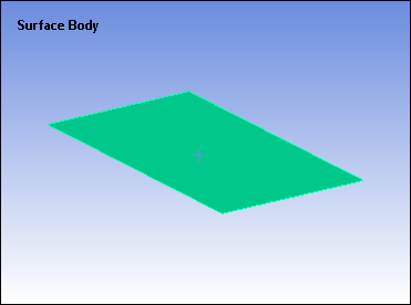
Highlight the Surface Body object and, in the Details, enter a value in the Thickness property. A value greater than 0 must be present in this field.
To specify the thickness of selected faces on a surface body:
Highlight the Geometry object and insert a Thickness object from the Geometry Context tab or right-click and select > .
Note: The Thickness object overwrites any element that is scoped to the selected surfaces that has thickness greater than 0 defined in the Details of the Surface Body object (See above).
Scope the Thickness to a desired geometric or mesh entity. The application supports Body, Face, and Element scoping.
Define the thickness as a constant (default), with a table, or as a function:
To define the thickness as a constant, enter the value in the Thickness field in the Details view.
To define the thickness with a table:
Click the Thickness property in the Details, then select from the flyout menu.
Set the Independent Variable in the Details to X, Y, or Z.
Select a Coordinate System. The Global Coordinate System (Cartesian) is the default.
Enter data in the Tabular Data window. The Graph window displays the variation of the thickness.
To define the thickness with a function:
Click the Thickness field in the Details, then click from the flyout menu.
Enter the function in the Thickness field. (Example: 45+10*x/591)
Adjust properties in the Graph Controls category as needed:
Number of Segments - The function is graphed with a default value of 200 line segments. You can change this value to better visualize the function.
Range Minimum - The minimum range of the graph.
Range Maximum - The maximum range of the graph.
Set the desired shell offset.
Review the requirements and limitations for this feature in the notes topic below.
Thickness Display Options
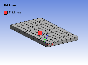
In the Geometry window, the application draws the thickness value you specify in the Thickness property when you 1) select the Show Mesh option and the Thick Shells and Beams option, 2) when you have the Mesh object selected, or 3) when you have a result selected. An example of this display is shown below. As illustrated, there is a Surface Body with no thickness and a Thickness object selected with a Thickness property value of 20mm displayed using the Show Mesh and Thick Shells and Beams options.
 |  |
Important: This display feature is not supported when you 1) scope the Thickness object to Elements and 2) specify the Thickness property using the Tabular or Function options.
Note:
Surface body thicknesses must be greater than zero. Failures will be detected by the solver.
When importing surfaces bodies from DesignModeler, the associated thickness is automatically included with the import. See Importing Surface Body Thickness for details.
When you specify a Thickness or Layered Section object, the Volume, Mass, Centroid, and Moment of Inertia properties of the geometry-based objects, automatically display the value "NA" because there is not a constant value to report.
For the following, the nominal thickness of the body is used as opposed to the thickness controlled by the Thickness objects being added (Thickness, Layered Thickness, Imported Layered Thickness):
Meshing: during the meshing process, auto-detection based on surface body thickness, automatic pinch controls, surface body thickness used as mesh merging tolerance.
Solution: Heuristics used in beam properties for spot welds as well as moments applied to vertices.
Thickness objects are not supported for rigid bodies.
Variable thickness is displayed only for mesh and result displays. Location probes, Path scoped results, and Surface scoped results do not display nor account for variable thickness. They assume constant thickness.
If multiple Thickness objects are applied to the same face, only those properties related to the last defined object will be sent to the solver, regardless of whether the object was defined in DesignModeler or in Mechanical. See Specifying Faces With Multiple Thicknesses and Layers for details.
You can import thicknesses from an upstream system. Basic setup steps are given below. You can find more information on mapping data in the Mechanical application in the appendix (Appendix B: Data Transfer Mapping and Validation).
Note: Thickness import is supported for 3D shell bodies or planar 2D bodies using Plane Stress. The Mechanical APDL Solver for 3D shell bodies will use the nodal thicknesses directly via the SECFUNCTION command. For the Explicit Solver or MAPDL solver for 2D bodies, the element's nodal thicknesses are converted to an average element thickness.
To import thicknesses from an upstream system:
In the project schematic, create a link between the Solution cell of a system and the Model cell of an upstream system.
Attach geometry to the analysis system, and then double-click Model cell to open Mechanical. An Imported Thickness folder is added under the Geometry folder and an imported thickness is added to the Imported Thickness folder, by default.
Select the appropriate options in the Details.
Select Imported Thickness and select Import Thickness from the context menu.