


Check the box next to the Spray Model node to enable sprays in your simulation. Sprays are composed of a large amount of liquid droplets. In internal combustion engines, they are typically formed during the liquid fuel injection processes. Ansys Forte uses Lagrangian spray models to track the formation and evolution of spray droplets. During the simulation, the concept of "parcel" represents a group of droplets with similar attributes in order to save the computational cost of tracking droplets.
Simulating sprays requires properly initializing the spray formation by specifying the type and parameters of the fuel injector and nozzle(s), or providing the necessary data at the nozzle exit. Selecting the proper spray models is also required. Both can be done on the Spray Model node.
First, selecting this node activates some general spray-model options, including Droplet Collision Model, Injectors, Nozzles, and Injections. For the Droplet Collision Model option, select Disabled, Radius of Influence Model or Collision Mesh Model, or Adaptive Collision Mesh Model and specify the associated options. Use Vaporization Model indicates that the injected liquid is allowed to vaporize (the default). For liquid-fueled engine cases this option is required.
Second, the Spray Model icon bar offers the following 4 icons that enable the definition of injectors, which can be solid-cone, hollow-cone, slit, or VOF injectors. Once the injector is created, you can specify the nozzle geometry and injection events, as described in Solid-Cone, Hollow-Cone, Slit, and VOF Injector Panels, as well as the additional spray-model settings specific to each of these injector types.
New Hollow Cone Injector
 : Creates a new hollow-cone injector and opens the Injector panel with
Hollow Cone options.
: Creates a new hollow-cone injector and opens the Injector panel with
Hollow Cone options.New Solid Cone Injector
 : Creates a new solid-cone injector and opens the Injector panel with
Solid Cone options.
: Creates a new solid-cone injector and opens the Injector panel with
Solid Cone options.New Slit Injector
 : Creates a new slit injector and opens the Injector panel with Slit
options.
: Creates a new slit injector and opens the Injector panel with Slit
options.New VOF Injector
 : Creates a new VOF injector and opens the Injector panel
with VOF options. A VOF (volume of fluid) injector represents one-way coupling between a VOF
simulation of internal nozzle flow and Ansys Forte’s Lagrangian spray simulation for solid
cone injections, in which user-supplied VOF input data are used to initialize the injected
Lagrangian spray parcels.
: Creates a new VOF injector and opens the Injector panel
with VOF options. A VOF (volume of fluid) injector represents one-way coupling between a VOF
simulation of internal nozzle flow and Ansys Forte’s Lagrangian spray simulation for solid
cone injections, in which user-supplied VOF input data are used to initialize the injected
Lagrangian spray parcels.
To create a spray injector, select the appropriate icon on the Spray Model icon bar (see Spray Model). The spray-model settings appropriate for that type of injector will then be displayed in the main injector Editor panel. In addition, the Injector icon bar offers the following icons that are used to define the nozzle holes and injection events associated with the injector:
Manage Injections
 : Provides worksheet for specifying injection properties.
New Nozzle
 : Adds a nozzle associated with the injector and opens the Nozzle panel
for configuring the new nozzle.
: Adds a nozzle associated with the injector and opens the Nozzle panel
for configuring the new nozzle.New Injection
 : Adds an Injection event associated with the injector (and nozzles) and
opens the Injection panel for configuring the injection in terms of timing and fuel
amount.
: Adds an Injection event associated with the injector (and nozzles) and
opens the Injection panel for configuring the injection in terms of timing and fuel
amount.Copy
 : Copies the injector along with any nozzles or injections associated
with the injector.
: Copies the injector along with any nozzles or injections associated
with the injector.Paste
 : Pastes the copied injector along with its defined nozzles and injection
events.
: Pastes the copied injector along with its defined nozzles and injection
events.
The spray-model settings are controlled in the Injector's main Editor panel. Use this panel to define the injector options, which control the fuel composition, temperature, and the ways that the spray parcels are initialized to simulate the fuel injection. The options for atomization and spray breakup models are also specified in this panel. There are several components to the spray breakup models that are described in more detail in the Ansys Forte Theory Manual. Default values are provided where appropriate. In the following, we briefly review both the general options and options specific to each type of injector.
Note: Ansys recommends keeping default settings for the spray model as a starting point.
The general settings that can be controlled here are as follows:
Composition: This controls the Fuel Composition. (See Mixture Editor for details of using the Mixture Editor.)
Time Frame: Set the timing offset for all associated injections.
Inflow Droplet Temperature: The initial temperature of injected droplets is typically near the coolant temperature in an engine environment. The value of 350 K is usually reasonable if an experimentally determined value is not known.
Droplet Size Distribution: Specify droplet size distribution to initialize spray injection.
For a Solid-Cone Injector, the specified droplet size distribution is applied at the nozzle exit. If the injector has a straight cylindrical nozzle passage, such as is commonly used for diesel fuel injection, the Uniform Size is recommended. In this case, an intact liquid core is assumed to exist at the nozzle exit, which is modeled by continuously injected large "blobs" of liquid droplets, and the initial droplet size is calculated based on the nozzle exit area and discharge coefficient. If the injector has a step-hole nozzle, such as is commonly used in gasoline direct-injection (GDI) engines, atomization is assumed to occur inside the nozzle. In this case, Ansys recommends a Rosin-Rammler or Log-normal statistical droplet size distribution to account for the effects of atomization.
The Rosin-Rammler probability density function has the general form:

(3–8)
where
 is the droplet diameter,
  is the shape parameter with typical range 2.0–5.0 for sprays in
engines, and
is the shape parameter with typical range 2.0–5.0 for sprays in
engines, and  is a characteristic mean drop size that is related to the Sauter mean
diameter through a gamma function:
is a characteristic mean drop size that is related to the Sauter mean
diameter through a gamma function:
(3–9)
The Sauter mean diameter is defined by:
 .
.To use the Rosin-Rammler distribution for a Solid-Cone Injector, the expected input parameters are the shape parameter (
) and the Sauter Mean Diameter of the droplet ( ).
).The Log-normal probability density function has the general form:

(3–10)
where parameters
 and
and  denote the mean and standard deviation of the normal distribution followed
by
denote the mean and standard deviation of the normal distribution followed
by  . They are related to the arithmetic mean (
 ) and standard deviation (
 ) of the log-normal distribution:
(3–11)
To use the Log-normal distribution for a Solid-Cone Injector, the expected input parameters are the arithmetic mean droplet diameter (
 ) and the ratio of the standard deviation over mean diameter
(
) and the ratio of the standard deviation over mean diameter
( ).
).
Note: There are two types of probability density function (PDF) for droplet size distribution: the number-based PDF and mass-based PDF. In Ansys Forte, fuel is injected with a number of "parcels," and each parcel contains one or multiple droplets. Whether the droplet size distribution function should be a number-based or mass-based PDF depends on the parcel specification. If the injected parcel count (or number of parcels) is specified, each parcel will contain an identical amount of mass (which is, the total fuel mass divided by the number of parcels injected), and is regarded as a fixed incremental of fuel mass. When specifying droplet size distribution for the parcels, it is better to use a mass-based PDF. If the droplet number density is specified, each parcel will contain the same number of droplets but likely different mass if a droplet size distribution is assumed. In this case, when specifying droplet size distribution for the parcels, it is better to use a number-based PDF.
For the Hollow-Cone Injector and Slit Injector, the specified droplet size distribution is applied when droplets are
formed from the liquid sheet breakup process. The detailed description of the physics and
modeling of the hollow cone spray formation process is provided in Forte Theory Manual, Linearized Instability Sheet Atomization (LISA) Model. The process of fan
spray formation from a slit injector is described in Fan Spray Models in the Ansys Forte Theory Manual. If the Uniform Size option is used, initial droplet size will be calculated by
Forte Theory Manual, Equation 6–64.
If Rosin-Rammler Distribution is used, input of the shape
parameter () is required and input of the Sauter Mean Diameter () is optional. If is not provided, it will be calculated by Equation 6–64
in the Forte Theory Manual. If it is provided, it will
override the prediction from the liquid sheet breakup model. Ansys recommends use of Rosin-Rammler Distribution without specifying . Similarly, if Log-normal Distribution is
used, input of the ratio of the standard deviation over the mean diameter () is required and input of the mean droplet diameter () is optional. If is not provided, it will be calculated by Equation 6–64
in the Forte Theory Manual.
For the Solid-cone Injector, there are several settings options that are specific to this type of injector, including options for specifying injected parcel count and several spray-model parameters controlling the initial injection velocity and droplet breakup behavior. In general, default settings are recommended as a good starting point. Options include:
Injection Type: Select whether the injection is pulsed or continuous. For continuous injection, the injected parcel count can only be specified through the Droplet Density option, where droplet density is defined as the number of droplets in each injected parcel.
Parcel Specification: Specify the number of injected parcels for either a pulsed injection or a continuous injection. For a pulsed injection, specify either the total number of injected parcels for the whole injection duration or specify the droplet number density in an injected parcel. When the number of parcels is specified, this number is for the first nozzle of this injector. If the injector contains more than one nozzle, the injected parcel count through the other nozzles will be scaled based on the nozzle exit area ratio. When the droplet number density is specified, this number density will be converted into injected parcel count based on the total injected mass and the mass of an injected droplet. A continuous injection can only use the Droplet Density option.
Note: The Injected Parcel Count is the total number of spray parcels to be injected through one injector nozzle. If there are multiple nozzles in the injector, the value specified is for the first nozzle. Suggested values are: 2000–5000 for each solid cone spray plume.
Spray Initialization: The spray can be initialized using an empirically derived Discharge Coefficient, or using a more detailed Nozzle-flow Model. When the default discharge coefficient initialization model is selected, only a value for the discharge coefficient is required. For the nozzle-flow model, two relative length scales are required, which are described in the Ansys Forte Theory Manual. Note that when the nozzle-flow model is selected, the spray cone angle will also be calculated along with the effective discharge coefficient.
On the Editor panel, the Cone Angle is specified for the injector. Note that this input is not used for the case when the nozzle-flow model option is selected with a solid-cone injector. In all other cases it is required input. The cone angle can be specified in two ways: as a user-specified constant value, or by using a correlation. The correlation is created based on validation data over a wide range of conditions, especially flash-boiling conditions. Since the flash-boiling injection condition is typically associated with a wildly expanding cone angle, the cone angle correlation option is recommended for simulating flash-boiling conditions. Details of the cone angle correlation are described in the Empirical Nozzle Discharge Coefficient and Spray Angle in the Ansys Forte Theory Manual.
KH Model Constants: These parameters are used in the Kelvin-Helmholtz (KH) droplet-breakup model, which is mainly applied in the near-nozzle liquid core region in solid-cone sprays. Note that this breakup model generates new child parcels to account for the small droplets shed from the liquid core. Impose SMR Conservation in KH Breakup is an option used in the child parcel generation process, and is turned OFF by default.
RT Model Constants: These parameters are used in the Rayleigh-Taylor (RT) droplet-breakup model. This breakup model is applied in the region beyond the "breakup length," which is a certain distance measured from the nozzle exit within which a liquid core is considered to exist in solid-cone sprays. Beyond the breakup length, the RT model applies to spray parcels and is expected to significantly reduce the averaged droplet size.
Use Gas Jet Model: This option helps to reduce mesh-size and time-step dependency in the spray penetration and droplet size prediction. It is ON by default.
The Hollow-Cone Injector and Slit Injector also have several settings options that are specific to defining the spray behavior for hollow-cone injections. As with the solid-cone spray settings, default settings are recommended as a starting point. Options include:
Injected Parcel Count Option: Specify how the number of injected parcels is specified. The Number of Parcels option specifies the total number of injected parcels for the whole injection duration and this option cannot be used with continuous injection. The Parcel Count Per Time and Parcel Count Per Mass options are for the convenience of setting up continuous injections, which specify the number of injected parcels per unit simulation time and per unit injected mass, respectively. These two options can be used with both pulsed and continuous injections.
Note: For typical pulsed injections used in IC engine applications, suggested values for total number of injected parcels are 1.0E4 for a hollow cone spray, and 3.0E4 for a fan spray (slit injector).
Recommended values for parcel count per unit time and parcel count per unit mass are 5.0E4 1/sec and 2.0E5 1/g, respectively, for a hollow cone injector. The values can be two to three times larger for a slit injector.
LISA Spray Model Options: Parameters are provided for the LISA spray model. The Breakup Length Model Constant controls the breakup length of the liquid sheet during the spray formation processes.
Injection Pressure: This should be the injection pressure in the sac volume of the injector. It is used to calculate the discharge coefficient.
Mean Cone Angle: For Hollow-Cone sprays only. This parameter controls the opening angle of the hollow-cone spray shape. Figure 3.14: Definition of mean cone angle and liquid jet thickness in a hollow-cone spray.
Liquid Jet Thickness: For Hollow-Cone sprays only. This prescribes the spreading angle of the spray layer. Figure 3.14: Definition of mean cone angle and liquid jet thickness in a hollow-cone spray.
Model Slug Flow: Select this option to account for the slug flow (the flow of residual fuel left in the injector from the previous injection). The slug flow is modeled as a small solid-cone spray. It is typically a very small portion of the total fuel flow and usually is not modeled.
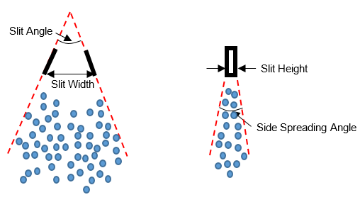
Slit Angle: For fan sprays only. This is the opening angle of the Slit Injector nozzle, and it also defines the initial fan angle of the spray. See Figure 3.15: Definition of several injection and nozzle parameters for slit injectors (Left: front view; Right: side view) (Left).
Side Spreading Angle: For fan sprays only. This parameter determines the dispersion angle of sprays with respect to the fan plane. See Figure 3.15: Definition of several injection and nozzle parameters for slit injectors (Left: front view; Right: side view) (Right).
Inwardly Opening Nozzle: This check box is only relevant to hollow cone injector, used to specify the opening direction of the pintle of the nozzle. For an inwardly opening nozzle, the pintle retreats toward the inside of the injector when the flow passage opens. Most pressure-swirl typed injectors are inwardly opening. If this box is unchecked, the nozzle is treated as an outwardly opening nozzle, meaning that the pintle protrudes towards the outside of the injector when it is lifted to open the flow passage. In modeling, the difference is that a fraction of injected parcels is allowed to collapse towards the interior of the hollow-cone structure in an inwardly opening nozzle.
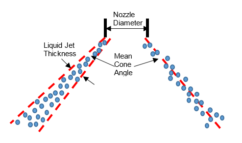
Figure 3.15: Definition of several injection and nozzle parameters for slit injectors (Left: front view; Right: side view)
The VOF Injector requires additional input information about the VOF input data and the mapping of location and velocity parameters between the VOF simulation and the Lagrangian spray simulation:
VOF Input File is used to specify the name of the VOF input data file. The location of the VOF input file is specified using an environment variable
FORTE_VOF_PATH. Ansys Forte provides a default value for this path. You can either copy the VOF input file to the default location or modifyFORTE_VOF_PATHto point to the VOF input file. Both absolute path and relative path are supported. IfFORTE_VOF_PATHis undefined, Forte will try to find the input file on the local path, that is, within the Run folder. However, ifFORTE_VOF_PATHis defined and points to a location where the input file does not exist, Forte will not attempt to search the local path. Instead, it will report an error and stop the calculation. The format of the VOF input file is explained in VOF Input File Format.VOF Start Time specifies when to begin to pull data from the VOF input file. This input parameter refers to the time values contained in the VOF input file that are used to mark each VOF data set.
Injector Reference Frame in VOF specifies a coordinate system for marking the injector’s location and orientation in the VOF simulation framework. This reference frame combined with the Injector Reference Frame in Lagrangian Spray are used to map location and orientation parameters from the VOF framework to Forte’s Lagrangian spray simulation framework. The location and orientation of the injector and all its nozzles in these two reference frames are required to be consistent with respect to their own simulation framework. Ideally, the origins of the reference frames should anchor the same point on the injector’s axis, and one of the coordinate axes should be aligned with the injector axis.
Injection Timing of Lagrangian Spray: Since only one VOF input file can be specified for a VOF injector, the Start of Injection (SOI) timing is exposed on the Injector setup panel, and there is no need to add Injection panels as used in other types of injectors. Duration of Injection (DOI) is calculated based on the VOF Start Time and the time value of the last data set in the VOF data file. The total injected liquid mass and injection profile are both derived from the VOF input data.
Each VOF Injector can have multiple Nozzles. For each nozzle, in addition to the nozzle exit’s Location, Spray Direction, and Nozzle Size, there are several Spray Parcel Initialization Controls:
Liquid Volume Fraction Threshold: If the liquid volume fraction in an VOF CFD cell exceeds this threshold value, Lagrangian spray parcels will be initialized from this cell. A smaller value will result in more injected parcels.
Max Injected Parcel Mass: Controls the maximum mass of an injected parcel. For each VOF CFD cell that will emit spray parcels, at least one parcel will be formed. If the total liquid mass from this cell exceeds this maximum parcel mass control, the total mass will be split into multiple parcels. A smaller value of this control will result in more injected parcels.
Min Injected Parcel Mass: Controls the minimum mass of an injected parcel. A VOF CFD cell will not emit spray parcels if the total liquid mass coming out of this cell is less than the min injected parcel mass. A smaller value will result in more injected parcels.
TKE Scaling Factor: The TKE scaling factor is used to modify the turbulent kinetic energy in a local VOF cell (in the VOF input data). The scaled TKE is then converted into turbulence velocity, which in turn is used to perturb the initial velocities of the injected spray parcels associated with this VOF cell.
An Injector requires one or more Injection events. To create an
injection, use the New Injection icon on the appropriate (Solid Cone, Hollow Cone, or Slit) Injector icon
bar. (See Solid-Cone, Hollow-Cone, Slit, and VOF Injector Panels.)
On the Injection Editor panel using a Pulsed injection, the Timing Option
allows you to specify the injection's Start and
Duration in terms of Time (relative to the start of
simulation) or Crank Angle (assuming a slider-crank boundary motion is
defined in the project). For a CA-based start-of-injection
timing used in engine cases, you can select the Crank Angle
Option as Cyclic or Global. The Cyclic option is helpful in
specifying injection that is repetitive in a multi-engine-cycle simulation. In this case, the
user-supplied Start crank angle value will be converted to fit in the
range of [0, 720) °CA (for 4-stroke engines) or [0, 360) °CA (for 2-stroke engines).
The injection timing will then be treated as cyclic and repeated on a 720-degree schedule
(4-stroke) or 360-degree schedule (2-stroke). You may choose to Use Global Crank
Angle Limits to impose a global crank angle range for the cyclic repetition, beyond
which the injection is not active. If the Crank Angle Option
is Global, no cyclic conversion is made on the user-supplied
start crank angle value.
The panel also provides options to edit or create a Velocity Profile
(by clicking the Edit ![]() icon and specifying the Total Injected Mass. The
Velocity Profile option opens the Profile Editor (see Profile Editor) where you can define the profile
manually or import data describing the injection shape.
icon and specifying the Total Injected Mass. The
Velocity Profile option opens the Profile Editor (see Profile Editor) where you can define the profile
manually or import data describing the injection shape.
The Injection Type parameter specifies the injection type as either Pulsed or Continuous. For Pulsed injection, also specify the injection Timing Option (start and duration), Total Injected Mass, as well as an injection Velocity Profile. For Continuous injection, specify the Mass Flow Rate.
Note:
In cases that contain periodic or symmetric boundaries, the nozzles added in the User Interface are for the meshed sector (or meshed domain) only, but these nozzles are assumed to be duplicated on all the unmeshed sectors in the full 360-degree domain. For a solid-cone injector, the Total Injected Mass specified in the User Interface is for all the nozzles in the 360-degree domain (in both meshed and unmeshed sectors). For a hollow-cone injector or a slit injector, the Total Injected Mass specified is for the nozzle(s) in the meshed sector only. For a VOF injector, total injected mass is specified through the VOF input file, and the mass is also for the nozzle(s) in the meshed sector only.
Avoid allowing the starting time or starting crank angle of the simulation to fall in the injection duration of any spray. When this happens to a spray, the injection will be ignored and no liquid will be injected for this spray.
An Injector must be associated with not only an Injection event but
also one or more nozzles. To create a nozzle, use the Injector icon bar (See Solid-Cone, Hollow-Cone, Slit, and VOF Injector Panels.)
Use the Nozzles panel to describe the nozzle characteristics in terms of location and
geometry. The Nozzles icon bar also offers 4 icons: Rename  , Copy , Paste
 ![]() , and Delete
, and Delete  . These allow you, for example, to create a new nozzle by copying and
pasting an existing one and then editing just the parameter that needs to change, such as
Spray Direction.
. These allow you, for example, to create a new nozzle by copying and
pasting an existing one and then editing just the parameter that needs to change, such as
Spray Direction.
Use the Reference Frame sub-panel to provide Location and Spray Direction of each nozzle hole. (See Reference Frames for more details on Reference Frames.)
Note: For converting nozzle orientations from KIVA: The Ansys Forte θ "theta" value is 180° - (KIVA's X-Z tilt). If X-Z=76, θ=180-76=104°. The φ "phi" value is: (the value of the sector wedge angle) - (X-Y tilt).
For Solid-Cone and Hollow-Cone injectors, the remaining geometric parameter for the nozzle is the Nozzle Area, which is the exit flow area. In Solid-Cone sprays, this is used to determine the initial Sauter Mean Diameter of the liquid droplets exiting the nozzle. For Hollow-Cone sprays, the nozzle area is an important parameter in determining the liquid sheet thickness and the spray formation as a result of sheet breakup. In both cases, you can also set Nozzle Diameter instead of Nozzle Area.
For Slit injectors, the Slit Height and Aspect Ratio are necessary inputs to specify the dimensions of a nozzle. The Aspect Ratio is defined as Slit Width divided by Slit Height. The nozzle area is associated to the Slit Height, Slit Width, and Slit Angle, as described in Fan Spray Models in the Ansys Forte Theory Manual. Considering the planar shape of a fan spray, a Nozzle Orientation Angle is needed to define the angle between the fan plane with respect to the direction of injection.
Note: For Hollow-Cone injectors, only one nozzle is allowed for each injector. For Solid-Cone
and Slit injectors, multiple nozzles are allowed for each injector, and the amount of mass
injected through each nozzle is split from the Total Injected
Mass based on the area of each nozzle with respect to the total nozzle area. When
creating multiple nozzles, it is often efficient to configure the first one and then use
Copy
and Paste
![]() to duplicate it, then modify the original configuration to correctly
specify the new nozzles.
to duplicate it, then modify the original configuration to correctly
specify the new nozzles.