


The nozzle-flow model describes the instantaneous flow conditions inside the nozzle. The purpose of the nozzle-flow model is to provide initial conditions for the spray model. The input parameters to the nozzle-flow model are:
mass flow rate
ambient gas pressure
physical properties of the liquid fuel
geometrical hole diameter
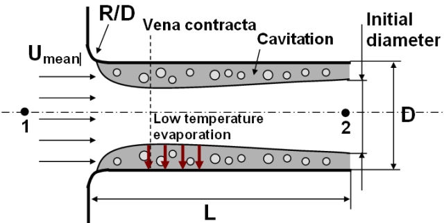
L/D ratio (see Figure 6.1: Flow through nozzle passage )
R/D ratio, where R is the radius of curvature of the injector entrance region (see Figure 6.1: Flow through nozzle passage )
Using these inputs, the nozzle-flow model determines the instantaneous discharge coefficient (Cd), spray angle, effective injection velocity and effective flow exit area. The flow exit area is then used to determine the initial injected liquid droplet size.
The volumetric mean flow velocity of the liquid fuel at the inlet of
the nozzle passage,  , can be calculated as
 | (6–1) |
where  is fuel mass flow rate,
  is liquid fuel density, A is nozzle cross-sectional
area, and D is nozzle diameter.
is liquid fuel density, A is nozzle cross-sectional
area, and D is nozzle diameter.
The mean mass flow through the nozzle exit is always lower than that
predicted by the Bernoulli equation, because of flow losses. The losses are caused by the
acceleration and formation of the velocity profile at the inlet, the expansion after the vena
contracta, and the wall friction. To quantify this difference, the discharge coefficient,
 , is defined as:
 | (6–2) |
where p 1 and p 2 are pressures at location 1 and 2, respectively, in Figure 6.1: Flow through nozzle passage .
By using tabulated inlet loss coefficients (K inlet) and the Blasius or the laminar equation for wall friction, the discharge coefficient is given by:
 | (6–3) |
 | (6–4) |
and Re D is the Reynolds number based on nozzle diameter.
A first estimation of the inlet pressure, p 1 , for a turbulent flow yields:
 | (6–5) |
Next Ansys Forte checks whether the flow under this condition is already cavitating. Assuming a flat velocity profile, and using Nurick’s expression for the size of the contraction (Figure 6.1: Flow through nozzle passage ), continuity gives the velocity at the smallest flow area:
 | (6–6) |
 | (6–7) |
In the case of cavitation the potential flow theory allows the application of the Bernoulli equation from point 1 to c without any losses:
 | (6–8) |
If p vena is lower than vapor pressure p vapor, it is assumed that the flow must be fully cavitating and a new inlet pressure and discharge coefficient are calculated by:
 | (6–9) |
 | (6–10) |
In the cases of non-cavitating turbulent flows, the exit velocity of the droplets is set equal to the mean velocity, U mean, and the diameter of the jet at the nozzle exit is equal to the nozzle diameter.
When the nozzle is cavitating, those values are calculated as:
 | (6–11) |
 | (6–12) |
 | (6–13) |
The spray angle in the nozzle flow model is estimated using an
aerodynamic model. This approach is based on Taylor’s analysis of high-speed liquid
breakup due to the unstable growth of surface waves and the resulting mass shedding. In this
approach, the spray angle,  , is expressed as:
 | (6–14) |
Where A is 3+0.28( L/D) and L/D is the length-to-diameter ratio of the nozzle. The function f(T) is approximated by
 | (6–15) |
Instead of applying the nozzle-flow model, you can also specify empirical constant values for discharge coefficient and spray angle. The empirical discharge coefficient is then used to calculate the effective injection velocity and initial drop size at the nozzle exit.
Two options are provided for specifying the spray cone angle: one is user-specified constant value, the other is using a correlation. For sprays not involving flash boiling, the user-specified constant value is an acceptable option, and the default range 12° to 15° is adequate for typical solid cone sprays.
The cone angle correlation is generated based on spray simulation validation data over a wide range of conditions, especially flash boiling conditions. Since the flash-boiling injection condition is typically associated with a wildly expanding cone angle, the cone angle correlation option is recommended for simulating flash boiling conditions. The correlation takes the form of a quadratic function:
 | (6–16) |
In which  is a function of several other physical parameters:
 | (6–17) |
 ,
,  , and
, and  represent the pressure ratio, dimensionless surface tension, and fuel
molecular weight:
represent the pressure ratio, dimensionless surface tension, and fuel
molecular weight:
 | (6–18) |
 | (6–19) |
where  ,
,  ,
,  ,
,  represent fuel saturation pressure at injection temperature of
 , ambient gas pressure, surface tension, and Boltzmann constant, respectively.
 is the molecular surface area defined as
  , and
, and  is the liquid molecular volume.