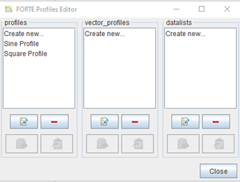
Whenever an item in an Editor panel requires or allows profile data, the
Edit Profile ![]() button to the right of the selection will open the Profile Editor. A
general link to the Profile Editor is also provided as the Profiles command
on the Edit menu and the Profile Editor button on the toolbar. The Profile
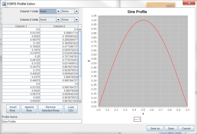
Editor (Figure 2.9: Profile Editor with data imported from a CSV file
) allows you to manually enter tabular data into
columns and rows, or you can paste into the columns tabulated numbers that have been cut from
Microsoft ® Excel ® or a similar
program. It also provides sine and square profiles ready to use or modify by clicking the
buttons in the two-column Profile list (Figure 2.9: Profile Editor with data imported from a CSV file). Once you decide on the profile type you
want, click the type or Create new... and then the pencil button to open
the Profile Editor interface.
button to the right of the selection will open the Profile Editor. A
general link to the Profile Editor is also provided as the Profiles command
on the Edit menu and the Profile Editor button on the toolbar. The Profile
Editor (Figure 2.9: Profile Editor with data imported from a CSV file
) allows you to manually enter tabular data into
columns and rows, or you can paste into the columns tabulated numbers that have been cut from
Microsoft ® Excel ® or a similar
program. It also provides sine and square profiles ready to use or modify by clicking the
buttons in the two-column Profile list (Figure 2.9: Profile Editor with data imported from a CSV file). Once you decide on the profile type you
want, click the type or Create new... and then the pencil button to open
the Profile Editor interface.
To paste text from an external table, first set the proper units for the X and Y columns of the profile. Then copy the table text you want to enter into Ansys Forte from the source program (such as Excel), use the "select all" command (Ctrl-A) in the Ansys Forte table, and then Paste (Ctrl-V). Alternatively, you can use the external program to save the data to a comma-separated values (CSV) text file, and then use the Import from CSV option. Once the data is entered into the columns, a plot of the profile should appear in the plot panel within the Profile Editor panel as shown in Figure 2.9: Profile Editor with data imported from a CSV file . At the bottom left of the panel, you can change the name of the profile and then use the buttons on the lower right to Save the results to the project. This will return you to the Editor panel from which the Profile Editor was launched. Make sure that the newly edited or created profile is now selected for the desired option in the Editor panel.
There are three types of profiles, which can be used for different purposes:
Profiles: This type of profile contains two columns. The first column is typically crank angle or time. The second column is typically physical quantities.
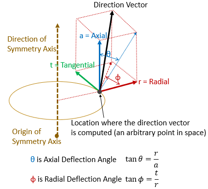
Vector Profiles: This type of profile contains four columns. The first column is typically crank angle or time. Columns 2 to 4 contain the three components of a vector. The vector can be a Position vector in Cartesian, Cylindrical, or Spherical coordinate systems. It can also be a direction vector. The Direction option is for specifying a simple direction vector in Cartesian coordinate system. The “ Direction, Axisymmetric option is for defining an axisymmetric vector pattern, mainly for velocities (Figure 2.10: Axisymmetric Direction Vector Pattern). For this option, you can specify the axisymmetric axis by its origin and direction and specify the Radial, Tangential, and Axial components of a vector with respect to the axisymmetric axis. For an arbitrary location in space, the final direction vector can be defined based on its location relative to the axisymmetric axis. If the input parameters available are the Axial and Radial deflection angles as shown in the figure, you can convert these two angles to the (Radial, Tangential, Axial) vector using the correlations listed in the figure. In doing this conversion, make sure you consider the special cases when θ or Φ equals 90°, which correspond to the conditions of a = 0 and r = 0. respectively. For both "Direction" and "Direction, Axisymmetric" options, the input vectors are not required to be normalized, but it is recommended to provide them as unit vectors.
Datalists: This type of profile contains only one column.
When a profile is used to provide a time-varying profile of certain physical quantity, the first column should be crank angle for crank angle-based simulation and time for time-based simulation. In either case, the profile may be treated as cyclic in certain use cases. On the UI panels where cyclic profiles are allowed, additional input parameters will be exposed for specifying the cyclic feature.
For crank angle-based profiles, the following parameters are exposed:
Repeat Profile Each Cycle: If this box is checked, the profile will be adjusted to fit within the cyclic range of 0-360 crank angle degrees for two-stroke engine or 0-720 crank angle degrees for four-stroke engine. A crank angle query outside of the cyclic range will be converted into a value within the cyclic range before being used in the temporal profile lookup. If this box is unchecked, for an out-of-cyclic-range crank angle query, the profile lookup will return the variable value at the profile boundary closest to this query.
Use Global Crank Angle Limits: Turn on this option to limit the cyclic-and-repeat treatment to be active only within a specified global crank angle range.
Global Start Angle and Global End Angle: These two inputs are global crank angle limits defining the start and end of the cyclic range. For a crank angle query outside of these limits, the profile lookup will first locate one of these two global crank angle limits closest to the query. Then, this limit value is converted into the cyclic range and the converted cyclic value is used in the profile lookup.
For time-based profiles, the following check box may be exposed:
Treat Profile As Cyclic: If this box is checked, the profile will repeat itself in a cyclic pattern after the time query goes beyond the last tabulation entry. The range of the cyclic profile goes from t = 0 second to the last tabulation entry. During profile lookup, a query time is first converted into its own time frame, and then converted to a value that fits in the cylcic range before being used in the profile lookup. The recommended practice for creating a cyclic time profile is to include an entry for t=0 second and make sure its variable value matches that of the last entry. If the profile does not contain an entry at t=0 second, the variable value at t=0 second will be assumed to be the same as that of the last tabulated entry. If an entry at t=0 second is provided but the tabulated variable values at t=0 second and at the last entry do not match, the value of the last entry will be used as the first point in repeated cycles. If the profile is non-cyclic, a query time beyond the last tabulation point will return the variable value of the last entry during profile lookup.


