The following are best practices for FSI (fluid-structure interaction) cases involving Fluent and Mechanical:
Important: Prior to connecting a Fluent Solution cell to a Mechanical (Static Structural) Setup cell for 1-way FSI, run the Fluent solver for a single iteration. This generates the required CDAT file, making CFD surfaces available for consumption in Mechanical.
In general terms, contact detection determines where the computed mesh motion will result in contact of a moving surface with other surrounding surfaces. However, the Mechanical and Fluent solvers each define it a bit differently. For Mechanical, it refers to surfaces/bodies coming into physical contact, while for Fluent, it refers to what Fluent does when two surfaces come into close proximity (that is, flow blockage).
Contact detection is often used in FSI simulations requiring flow blockage – that is, cases for which you need to restrict the flow or limit the movement between boundaries – such as valve applications with highly flexible flow-control geometry. Using the same geometry, you can apply an offset/proximity threshold to both the fluid and structural sides of the analysis. The proximity threshold applied in Fluent (as described in Contact Detection Settings) specifies a tolerance within which cells are flagged for the application of flow resistance, while the offset specified in Mechanical (as described in Geometric Modification in the Mechanical User's Guide) restricts the moving boundary by a certain distance from a surrounding surface, so that a flow restriction can be applied in that cavity. This also prevents the fluid mesh from folding if the mesh is pinched between the moving boundary and a surrounding surface. The offset applied to the structural side is intended to mirror the movement restriction applied on the fluid side, so that both bodies are aligned during coupling. This simplifies the process because no modification to the geometry or mesh is required.
The recommended sequence for setting up contact detection in a coupled FSI problem between a Fluent-Mechanical coupling is summarized below:
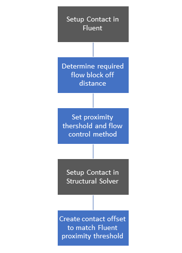
Set up contact detection in the Fluent solver.
Identify the distance that will be required to block off the flow. (To do this, you may need to run one-way FSI analysis to test how close the moving boundary can get to surrounding surfaces without causing the mesh to fold.)
Using the obtained distance, set the contact detection tolerance — that is, a proximity threshold to detect when the moving boundary is within a specified tolerance of the surrounding surface.
Set up contact marks or contact zones to block or restrict the flow between the offset, using the flow control settings provided by the Fluent solver.
Choose a flow control method. Ansys recommends that you use contact numerics. Contact numerics mark cells within the proximity threshold set between two or more faces and blocks the flow in the marked cells.
For more information, see Contact Detection Settings.
Set up contact detection in the Mechanical solver.
In the structural solver, configure contact detection settings to match those of the Fluent solver.
For more information, see Geometric Modification in the Mechanical User's Guide.
When trying to determine the appropriate contact detection distance and/or if contact is established in Fluent, it can be helpful to turn on contact marks rendering, as follows:
In the Fluent TUI, specify that contact cells should be rendered by entering the following text command:
/define/dynamic-mesh/controls/contact-parameters/render-contact-cells? yes
Verify the contact markings in the Contours dialog box, as follows:
Under Contours of , select Cell Info and Contact Markings.
Under Options, clear the Node Values check box.
In addition, it can be useful to set the verbosity for contact detection so as to determine when contact is established in the transcript. In the Fluent TUI, set verbosity by entering the following command:
/define/dynamic-mesh/controls/contact-parameters/verbosity 1
Diffusion-based smoothing is generally recommended, using the boundary distance diffusion function.
A diffusion parameter (α) = 1.5 is a good starting point, as it works well for absorbing the motion with the far field mesh.
If the boundary layer mesh deforms, increasing the diffusion parameter can further preserve the mesh close to the moving boundary.
If remeshing is not required Smoothing From Reference Position should be selected, specifically for periodic motion.
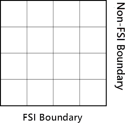
Although the first bullet point generally recommends diffusion-based smoothing, there are exceptions. As an example, consider the intersection between an FSI boundary and a non-FSI boundary, such as a flow outlet.
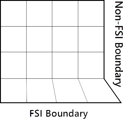
If diffusion-based smoothing is used, then the nodes on the non-FSI boundary will remain on its original surface. If the FSI boundary motion has a large tangential component (for example, displacement caused by thermal stresses), this can lead to a mesh wiggle on the non-FSI boundary:
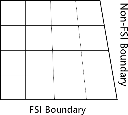
Better smoothing behavior will result by using linearly elastic smoothing or radial basis function smoothing, and setting the geometry definition for the non-FSI boundary to unspecified:
Recommended starting point for the remeshing minimum (Lmin) and maximum length scales (Lmax) are 0.4Lmin and 1.4Lmax.
Remeshing and smoothing should be enabled locally for all Dynamic Mesh Zones that are of type Deforming, this allows remeshing and smoothing to be applied to faces adjacent to the System Coupling Region.
It is also important to remember that there is no direct control over skewness and size criteria of the remeshed cells. Therefore, you can only indirectly control these criteria of the deformed mesh. For that reason, if the remeshed cells are not of adequate quality, you can further tighten the related criteria.
Identify where the mesh folding is occurring.
Open case file for the folded mesh and examine the Cell Volume contour for the domain. You can highlight the folded cells by setting the maximum range to 0, so that only cells with a negative volume are displayed. This can give an indication of what might be causing the mesh folding — that is, the time step size might be too large, or the dynamic zones may be set up incorrectly. For information on how to address cases where the prism layer is folding, see Deformed Prism Layers .
Rerun the case with smoothing and remeshing verbosity turned on. This may provide clues as to what is causing mesh folding.
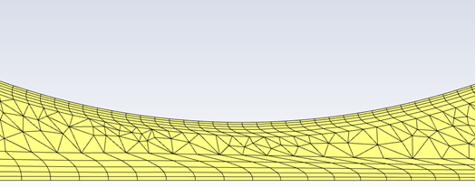
A deformed prism layer can quickly cause a case to fail due to the mesh folding. Fluent currently does not support the remeshing of prism layers. If a case exhibits deformation in the boundary layer due to large movement/deformation of the FSI regions, there are three main recommendations that depending on the case can resolve this pathology:
Increase the Diffusion Parameter to increase the mesh stiffness around the boundaries and cause regions away from the moving boundary to absorb more of the motion.
If the prism layer mesh around the moving body is uniform (i.e. constant number of prism mesh layers around the geometry), then Ansys recommends that you split the boundary layer mesh into a separate Cell Zone.
If the prism layer is not uniform (i.e., stair-stepping due to small gaps) and/or contact detection is required in Fluent, then the use of overset meshing is recommended. Overset meshing is also recommended for complex topologies.
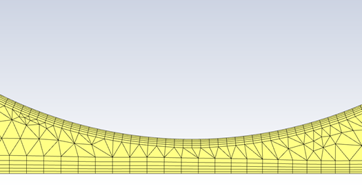
For cases that exhibit prism layer deformation/shearing (i.e., due to translational movement between two bodies in close proximity as shown in Figure 49.6: Skewed prism cells due to translational motion between two bodies in close proximity below), boundary Boundary Layer Smoothing Method can be implemented along with Region Face Meshing. Boundary Layer Smoothing preserves the boundary layer by applying the displacement vectors on the coupled face zone to the nodes of each cell in the boundary layer zone. This requires that the boundary layer mesh is split into a separate zone. As an example, we will go through the procedure of splitting the boundary layer mesh for the geometry shown below (Figure 49.7: Example geometry). As the geometry includes a prism layer mesh on the outside walls as well as the inside walls, they will need to be separated individually. It is important to note that Boundary Layer Smoothing is only applicable when using Spring-based Smoothing.
Split the prism layer cap to a separate cell zone condition to allow Region Face remeshing to be invoked:
Create a Boundary Cell Register with the required prism elements.
Right-click Solution>Cell Registers>New>Boundary
Use Cell Distance and highlight the boundary zone were the prism layers are located. The number of cells is set based on the number of prism layers.
Use the Boundary Cell Register to separate the prism layers into a separate cell zone.
Click Zones > Separate > Cells.
Select the register with the prism cells and the zone that you’d like to split.
Verify that the correct cell zones were created based on the cell registers and zones.
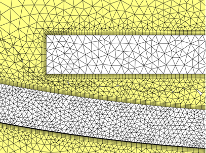
In this case we have split our single cell zone into three separate cell zones. The first cell zone contains the inner boundary layer mesh (Figure 49.8: Cell Zone containing the inner boundary layer mesh), the second cell zone contains the outer boundary layer mesh (Figure 49.9: Cell Zone containing the outer boundary layer mesh) and finally the third cell zone contains the interior mesh (Figure 49.8: Cell Zone containing the inner boundary layer mesh).
For the Dynamic Meshing settings, select Spring based smoothing as all other smoothing methods do not support Boundary Layer Smoothing (Deform Adjacent Boundary Layer with Zone) will not be available.
Turn on Region Face remeshing.
Turn off smoothing for the symmetry/wall regions. This prevents cells adjacent to moving wall from getting too stretched. Smoothing would still be conducted in the interior cells.
In the Dynamic Mesh Zones, set the moving prism layer cell zone as a rigid body:
By default, Rigid Body Dynamic Mesh Zones require a UDF to specify the mesh motion. Since the motion is provided by System Coupling, assign a “dummy UDF."
The dummy UDF is an empty UDF, as follows:
#include "udf.h"


DEFINE_GRID_MOTION(dummy_motion, domain, dt, time, dtime)

{

    return;

}
For the boundary layer mesh to move with the Coupled region, Deform Adjacent Boundary Layer with Zone must be turned on:
Setting the Cell Height in the Adjacent Zone is not required, since the prism layer mesh will not be remeshed.
Set the Cell Zone containing the interior mesh as Deforming, this will allow the tri/tet faces and cells (Figure 49.11: Prism layer mesh quality maintained for large deformations) to be remeshed.
Running the case again, we can see how the prism layer mesh is maintained using Boundary Layer Smoothing and only the interior cells are remeshed.
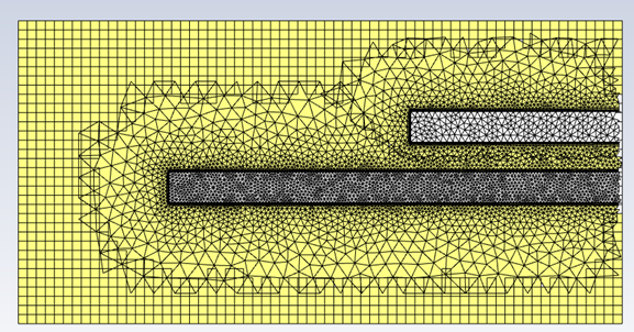
As previously mentioned, for complex topologies and/or if the prism layer is not uniform (i.e., stair-stepping due to small gaps), Ansys recommends the use of overset meshes. By having a separate mesh for the background and the components, the remeshing and smoothing parameters can be controlled for each component mesh. For example, the overset mesh below (Figure 49.12: Overset mesh generated using three separate meshes) is created using three separate meshes. A structured hexahedral mesh is used for the background, while a tetrahedral mesh is used for the two geometries.
The leading edge of the long rectangle rotates clockwise, creating a small gap between the short rectangle. If a single mesh was used for this case, the prism layer mesh around the two components deforms and causes the mesh to fold. This occurs as the prism layer mesh starts to absorb the deformation as the gap between the two geometries decreases. By having the components separately meshed, each components mesh absorbs the deformation in its far field, before mapping it back to the overset mesh, maintaining the prism layer mesh quality (Figure 49.13: Prism layer mesh quality is maintained).
The general workflow to setup an overset mesh case is as follows:
Split and remesh the required geometries.
Revise the time step size:
Consider the three time scales. Note that the smaller timescale is dominant.
Simulation
Mesh deformation
Overset meshing
The ideal time step size should be chosen such that the relative mesh motion does not exceed the length of the smallest cell at the overset interface for a given time step. The mesh length used for calculating the time step size should be restricted to cells in the overset overlap region.
It is important to not have large variations in mesh resolution in the motion path that could trigger large changes in the overset interface as the motion proceeds. The use of grid priorities can minimize large variations in the overset interface.
Choose the Overlap Minimization required:
A cell-volume-based method is recommended if the component mesh resolution is fine near walls and increases gradually away from walls and becomes similar in size to or larger than the background mesh.
Enter the following command into the Fluent TUI:
define/overset-interfaces/options/donor-priority-method 0
A boundary-distance-based method is recommended when overlapping meshes have uniform and nearly identical resolutions. Therefore, it is most suitable when two walls have small distance in between them.
Enter the following command into the Fluent TUI:
define/overset-interfaces/options/donor-priority-method 1
Create Overset interface and initialize solution:
The overset mesh is created during initialization; it can be viewed through Results > Graphics > Mesh by checking Overset under Options
Refer to Diagnosing Overset Interface Issues for more information.
For cases where interior cells are skewed due to translational and/or rotational movement (Figure 49.6: Skewed prism cells due to translational motion between two bodies in close proximity ) or remeshing resulting in elements that are too large or small, there are two main recommendations that depending on the case can resolve this pathology:
Use tighter criteria for the minimum and maximum length scales as well as skewness. In addition, decrease the Size Remeshing Interval to 1 so that remeshing based on size is triggered at every time step.
If the previous step did not resolve this, then enabling Region Face Remeshing. Region Face Remeshing will not trigger if a prism layer mesh is located in the same cell zone were remeshing needs to occur. Thus, you must split the prism layer mesh into a separate cell zone. Refer to the Deformed Prism Layers section for detailed instructions.
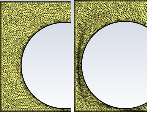
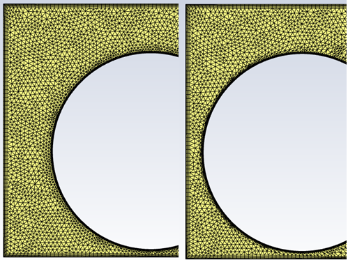
For the case shown below, setting tighter criteria for the minimum and maximum length scales to remesh every time step was not sufficient to produce a high-quality mesh in the gap (Figure 49.14: Original Mesh (left) and deformed mesh (right) with smoothing and remeshing enabled ). Since there is no direct control over skewness and size criteria of the remeshed cells, you can only indirectly control these criteria of the deformed mesh.
By using Region Face Remeshing, this allows more control over the size of the remeshed cells (Figure 49.15: Original Mesh (left) and deformed mesh (right) using smoothing and Region Face Remeshing). This is done by splitting or deleting the cells directly adjacent to the moving boundary based on the maximum and minimum length scales only. But as previously mentioned, the prism layer mesh has to be in a separate cell zone and treated as a rigid body.
Figure 49.15: Original Mesh (left) and deformed mesh (right) using smoothing and Region Face Remeshing
Note:
Overset meshes are not supported by CFD-Post. So, post processing must be handled directly in Fluent.
For overset meshes, volume integrals are taken over all solve cells in the domain. This results in double counting where solve cells overlap, leading to errors in volume integrals on overset meshes.
For cases where divergence in Fluent occurs because flow is blocked off at the beginning of the run (for example, a valve starting at closed position with contact). The following list offers recommendations for working with these types of cases:
Initialize the flow with zero velocity. This also prevents significant movement of the FSI region in the first coupling step, which can fold the mesh.
Ramping the inlet boundary condition can help with robustness. For details, see Velocity Inlet Boundary Conditions or Pressure Inlet Boundary Conditions
If the fluid is a gas such as air, using the ideal gas model (rather than treating it as incompressible) can aid with solution stability. For details, see Ideal Gas Law for Compressible Flows.
Note that these recommendations have an effect on the solution, as well as convergence behavior.


