The Turbo Workflow provides you with the basic steps to defining and refining the setup and solution of your turbomachinery simulation within Fluent.
You can access the turbomachinery guided workflow by selecting the Enable Workflow option in the Turbo Workflow drop-down menu in the Turbomachinery category of the Domain Ribbon.
![]() Domain → Turbomachinery
→ Turbo Workflow → Enable
Workflow
Domain → Turbomachinery
→ Turbo Workflow → Enable
Workflow
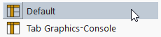
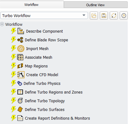
This exposes a Workflow tab, alongside the Outline View, where you can use the Turbo Workflow to begin your work. The Turbo Workflow provides you with a series of turbomachinery-specific workflow tasks. Your goal is to progress through each task in order to more easily analyze your turbomachinery problem and generate an accurate simulation.
Once you have completed the steps in the Turbo Workflow, you can review your simulation settings in the Outline View, and/or proceed on to calculate a solution and analyze the results of your turbomachinery simulation.
Note: The workflow is similar to the Fluent guided meshing workflows (Getting Started with the Fluent Guided Workflows). See Understanding Task States, Operating on Tasks, Grouping Tasks, or Editing Tasks for more information about working with and understanding tasks in the Fluent workflows.
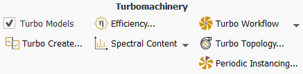
Additional options are available under the Turbo Workflow drop-down menu in the Ribbon:
Enable Workflow: exposes the Turbo Workflow in the Workflow tab.
Hide Workflow: removes the workflow from the graphical user interface.
Show Workflow: exposes the workflow tab in the graphical user interface.
Disable Workflow: removes the workflow tab and workflow-related information, while retaining settings performed in Fluent so far. Fluent will prompt you to make sure that you want to proceed.
This section describes the various tasks that are provided when using the Turbo Workflow:
- 14.1.1. Describing the Components of the Turbo Machine
- 14.1.2. Defining Your Blade Row Scope
- 14.1.3. Importing Your Mesh
- 14.1.4. Associating Your Mesh
- 14.1.5. Mapping Your Regions
- 14.1.6. Creating the CFD Model
- 14.1.7. Defining the Turbomachinery Physics
- 14.1.8. Defining the Turbomachinery Regions and Zones
- 14.1.9. Defining the Turbomachinery Topology
- 14.1.10. Defining Turbomachinery Surfaces
- 14.1.11. Creating Turbomachinery Report Definitions and Monitors
- 14.1.12. Text Command List for the Turbo Workflow
- 14.1.13. Editing Tasks in the Turbo Workflow
- 14.1.14. Saving and Loading Turbo Workflows
- 14.1.15. Applying Preferences to the Turbo Workflow
A turbomachine could have one or more turbomachine components, and each component has a unique set of information (number of rows, row type, and number of blades). Use the Describe Component task to describe a single component of the turbomachine system that you want to simulate. For example, you might want to simulate a full wheel axial compressor blade/row assembly where you have 26 internal guide vanes, 23 rotor blades, and 30 stator blades.
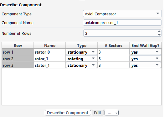
Specify the Component Type. You can have one of two types of turbomachinery components:
Axial Compressor or Axial Turbine
Axial components that are described by the number of rows (between 1 and 99) and the X, Y or Z axis of rotation. Each row could be either a stationary row (for example, inlet guide vanes (IGV), nozzle guide vane (NGV), stators) or a rotating row (for example, rotors). In addition to specifying the name and type for each row, you also need to define the number of blades for each row.
Radial Compressor or Radial Turbine
Similar to axial components, radial components are described by the number of rows (between 1 and 99) and the X, Y or Z axis of rotation. Each row could be either a stationary row (for example, inlet guide vanes (IGV), nozzle guide vane (NGV), stators) or a rotating row (for example, rotors). In addition to specifying the name and type for each row, you also need to define the number of blades for each row.
Specify the Component Name, or keep the default value.
Specify the Number of Rows, or keep the default value.
For each row:
Specify a Name or use the default name.
Specify the Type of motion as either stationary or rotating.
Specify the number of blade sectors (# Sectors), or keep the default value(s).
Use the Tip Gap? field to determine whether or not you need to allow for any spacing between the blade and the hub/shroud, or keep the default value(s). Non-conformal mesh interfaces are often placed here, so identifying this as yes will allow the non-conformal interface to be generated automatically.
By default, this option is set to Yes for rotor rows and No for stator rows. The tip gap is considered a hub gap when this option is set to Yes for stator rows.
Note: Read-only table cells (such as Name in this task) are indicated in gray, however, you can multiply-select and edit cells in the table using the context menu.
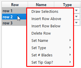
This allows you to draw the selected item(s) in the graphics window, insert a row above or below a single selected row, remove a single selected row, change the name of a single row, or create a name for a group of rows, change the type, the number of blades, and the tip gap presence. Note that inserting a row before or after another row always copies the properties and settings of the current row to the inserted row.
Once your selections are made, click the Describe Component button to apply your component description settings.
If you need to make adjustments to any of your settings in this task, click Edit, make your changes and click Update, or click Cancel to cancel your changes.
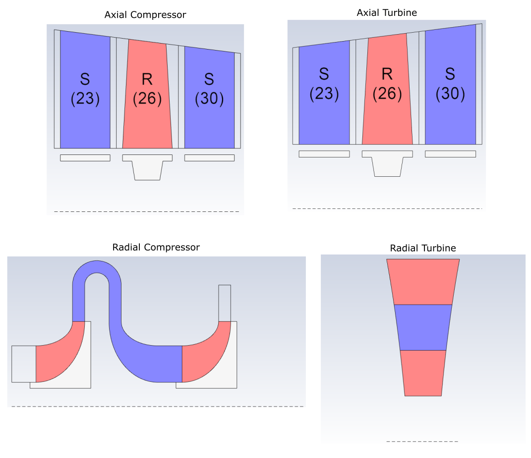
While describing your turbomachine, a 2D graphical schematic representation is made available in the graphics window for a single component (Figure 14.1: Examples of Schematics for Various Multi-Row Component Types):
Proceed to the next step in the workflow.
Use the Define Blade Row Scope task to specify which rows to include in your turbomachinery analysis. You must define a single contiguous set of rows. Indicate whether or not to include or exclude the row. You can elect to keep all or just a subset of the turbomachine system that you defined in the previous task.
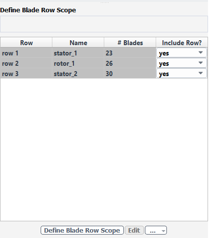
Review the information in the table, and make any changes as needed.
Once your selections are made, click the Define Blade Row Scope button to apply your settings.
If you need to make adjustments to any of your settings in this task, click Edit, make your changes and click Update, or click Cancel to cancel your changes.
The graphics window will display a basic 2D schematic for each component scope. For radial and axial components, the row color is grayed out if it is not included in the analysis.
Proceed to the next step in the workflow.
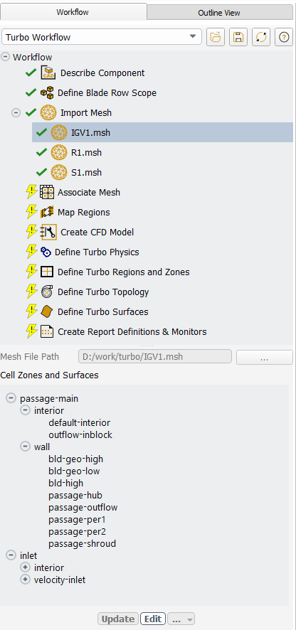
Use the Import Mesh task to supply the mesh for the rows you wish to include in the CFD model. You can import a single mesh file that includes all of the rows/passages/blades, or import multiple mesh files that represent each passage/blade.
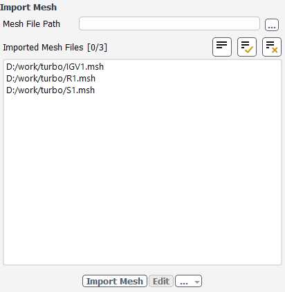
For the Mesh File Path field, provide a path and a name for the mesh or case file that you want to load into the task, or use the (…) button to browse for a specific file. Each file may contain several cell zones.
Standard Ansys mesh file types are supported, including
.msh,.msh.h5,.def,.cgns, and.gtm.Note: The workflow also supports importing meshes with multiple blade(s) and/or splitter(s) in a particular cell zone.
Once your selections are made, click the Import Mesh button and proceed to the next task.
For each loaded file, a child task will be created which shows the full path to the file. The child task also provides a tree view displaying the cell zones and their associated face zones.
If you need to make adjustments to any of your settings in this task, click Edit, make your changes and click Update, or click Cancel to cancel your changes. If a new mesh or case file is specified, the old file will be unloaded and the new file will be imported and displayed.
Proceed to the next step in the workflow.
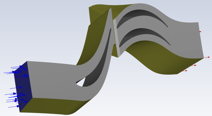
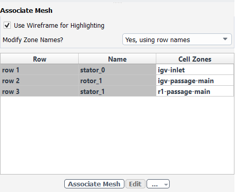
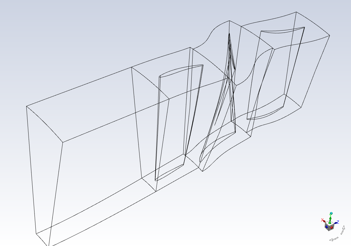
Use the Associate Mesh task to associate and map each cell zone from the imported mesh file(s) with the corresponding row of the turbomachine.
This will be helpful in later tasks where Fluent copies and stitches cell zones to create the full CFD model.
By default, the Use Wireframe for Highlighting option is selected so that the imported geometries are displayed in wireframe. Arrows are also used to indicate flow direction.
Use the Modify Zone Names? field to adjust how your zones names appear once this task is completed, depending on your preferences. When set to Yes, using row names, this field will change the associated cell (or face) zone name according to the corresponding Name. When set to Yes, using row numbers, this field will change the associated cell (or face) zone name according to the corresponding Row number. You can also choose No to keep the zone names as they are.
Say, for instance, the zone is called
s1-inflow-passageand it is located in the table where its Row is designated asrow3and its Name is designated asstator_1.For cell zones, Yes, using row names modifies the cell zone name entirely. For instance, the cell zone
s1-inflow-passagewill be modified tostator_1. When there are multiple zones, a numerical designation is added at the end of the name, such asstator_1.1for example.Likewise, if you select Yes, using row numbers, then the zone name will be changed to
row03:s1-inflow-passage.For face zones, Yes, using row names modifies the face zone name by adding the row name as a prefix. For instance, the face zone
s1-inflow-passagewill be modified tostator_1:s1-inflow-passage. When there are multiple zones, a numerical designation is added at the end of the name, such asstator_1.1:s1-inflow-passagefor example.Likewise, if you select Yes, using row numbers, then the zone name will be changed to
row03:s1-inflow-passage.
In the table, ensure that the selected Cell Zone has been properly assigned.
You are expected to assign one or more cell zones to each row. This information will be used for later tasks to copy and/or transform cell zones for each row and create the CFD model.
If any cell zone association changes are still required, click the corresponding table cell to make the change.
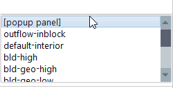
Use the cell's drop-down menu to choose from a limited list of potential cell zones.
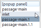
To choose from a potentially larger selection of cell zones, select the [popup panel] option to open the Select Cell Zones dialog, where all available associated and unassociated cell zones are listed. This dialog also allows you to filter and sort potentially large lists of cell zones. Associated zones can be assigned to be upstream or downstream as needed.
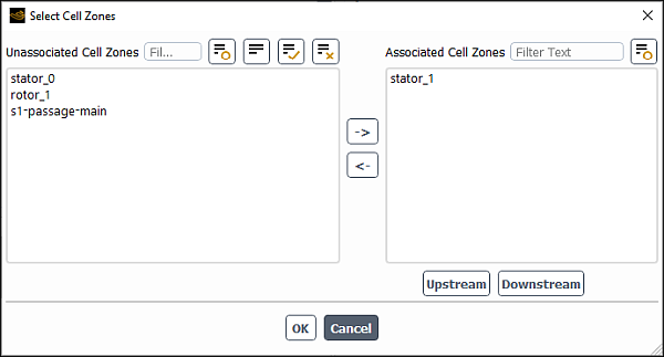
Make your selections in the dialog and click OK, or click Cancel to dismiss the dialog.
Once your selections are made, click the Associate Mesh button and proceed to the next task.
If you need to make adjustments to any of your settings in this task, click Edit, make your changes and click Update, or click Cancel to cancel your changes.
Proceed to the next step in the workflow.
For each original cell zone, use the Map Regions task to associate and map the corresponding face zones to ensure that the face zones correspond to the correct blade passage region.
This information will be used while defining boundary conditions and the turbo topology in Fluent.
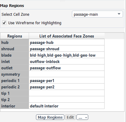
Use the Select Cell Zone field to select a particular zone for mapping its regions.
In the table provided, for each of the listed Regions, ensure the proper face zone(s) is selected under the List of Associated Face Zones.
Note: As you hover over items in the table, they are highlighted in the graphics window.
Once this task is updated, upon subsequent visits to this task, periodic zones are no longer highlighted as other surfaces are, since they will have been merged into different periodic zones. These highlighted periodic zones are visible in the Define Turbo Topology task, however, if you need to highlight them in this task, you will have to first undo your work in this task.
Note: Face zone mapping and assignment associations are based on those defined in the Fluent Preferences dialog (under the File menu), in the Turbo Workflow category.
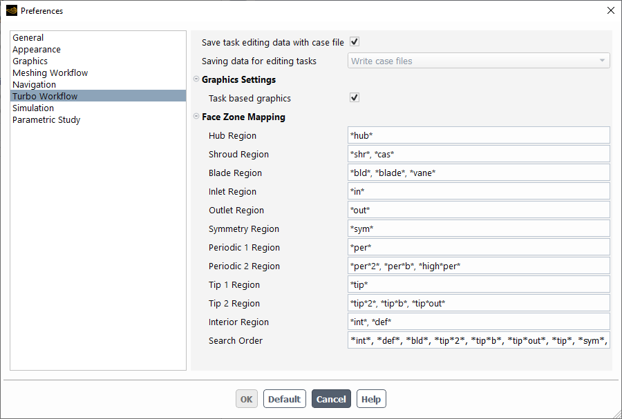
You can edit these associations according to your specific simulation requirements.
If any face zone association changes are still required, click the corresponding table cell to make the change.
Use the cell's drop-down menu to choose from a limited list of potential face zones.
To choose from a potentially larger selection of face zones, select the [popup panel] option to open the Select Face Zones dialog, where all available face zones are listed. This dialog also allows you to filter and sort potentially large lists of face zones.
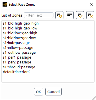
Make your selections in the dialog and click OK, or click Cancel to dismiss the dialog.
Once your selections are made, click the Map Regions button and proceed to the next task.
For each selected cell zone, a child task will be created that shows the mapped face zones for the corresponding region.
If you need to make adjustments to any of your settings in this task, click Edit, make your changes and click Update, or click Cancel to cancel your changes.
Note: If you have completed the Define Turbo Regions and Zones task, and need to edit the Map Regions task, you must first Revert and Edit the Create CFD Model task.
Proceed to the next step in the workflow.
Use the Create CFD Model task to formally create the 3D model of the turbomachine based on your inputs for the previous tasks. Use the graphics window to visually verify and ensure the CFD model is constructed properly.
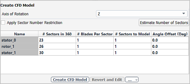
Specify the Axis of Rotation for the generated CFD turbomachine geometry.
Use the Apply Sector Number Restriction field to indicate whether you need to restrict the number of blade sectors to model. This will restrict the number of model blade sectors to factors of the number of actual blades.
Use the Estimate Number of Sectors button to have the workflow provide an estimation of the number of blade sectors, based on your imported geometry.
Note: Upon importing your mesh, the number of sectors can now be estimated based on the axis of rotation and the angle between the two periodic surfaces. This value, however, may differ from the value provided earlier in the Describe Component task where you might not have confidently known the number of blades for a specific component.
If the estimated number of sectors differs from the value provided in the Describe Component task, you should make the changes persistent and make the necessary changes in the Describe Component task accordingly.
If necessary, specify the Number Sectors in 360 to indicate the number of blade sectors for a full 360 degree geometry.
Specify the number of blades in a given sector for the CFD model (# Blades Per Sector).
Specify the number of modeled passages per row by specifying the number of sectors in the CFD model (# Sectors to Model) and/or any Angle Offset for each row, around the specified axis of rotation. For instance, you can choose to create a small or large portion of the full turbomachine, or the entire turbomachine, as needed.
In each case, once a value is entered, a preview of your changes appears in the graphics window without necessarily updating the task.
Once your selections are made, click the Create CFD Model button and proceed to the next task.
Note: Once this task is updated, zone names are appended with the appropriate sector number (even for single sectors), such that
passage, for example, becomespassage_01,passage_02, and so on.If you need to make adjustments to any of your settings in this task, click Revert and Edit, make your changes and click Update, or click Cancel to cancel your changes.
Note: If you have completed the Define Turbo Regions and Zones task, and need to edit the Map Regions task, you must first Revert and Edit the Create CFD Model task.
Proceed to the next step in the workflow.
Use the Define Turbo Physics task to specify the overall physics conditions of the turbomachinery simulation, such as the rotational speed, pressure, and the material assignment for the working fluid.
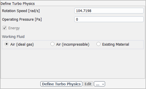
Specify the Rotation Speed, or keep the default value.
Specify the Operating Pressure, or keep the default value.
Specify whether Energy, or temperature effects, need to be considered.
Specify the Working Fluid as either Air (ideal gas), Air (incompressible), or an Existing Material.
If you select Air (incompressible), then you can also provide the Air Density, or keep the default value.
If you select Existing Material, then you can choose to use the currently available default fluid material (air) from the Existing Fluid Material drop-down list, or use the Create/Edit... button to create additional materials or edit existing material(s).
Once your selections are made, click the Define Turbo Physics button and proceed to the next task.
If you need to make adjustments to any of your settings in this task, click Edit, make your changes and click Update, or click Cancel to cancel your changes.
Proceed to the next step in the workflow.
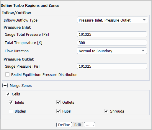
Use the Define Turbo Regions and Zones task to specify the overall regional or zonal operating conditions of the turbomachinery simulation. In this task, you can specify the type of flow and various pressure specifications. You can also determine if/how cell zones are to be merged. By default, zones are merged to simplify boundary condition input, and based on the target turbo model requirements.
Note: While this task uses basic default values for turbomachinery-related properties, if you require advanced settings (such as profile support), you can access and edit them accordingly directly through the Outline View.
Specify the Inlet/Outlet Type where inlet and outlet conditions are defined by combinations of pressure and mass flow specifications. Choice include
Pressure Inlet, Pressure Outlet - where both inlet and outlet conditions are specified through pressure values. If you choose this option, then you must specify the following as well:
Under Pressure Inlet:
Specify the Gauge Static Pressure at the inlet, or keep the default value.
Specify the Total Temperature at the inlet, or keep the default value.
Specify the Flow Direction at the inlet. Choices include the default Normal to Boundary, or you can specify the Cartesian choices of X, Y, and Z directions, or the Cylindrical choices of Radial, Tangential, and Axial directions
Under Pressure Outlet:
Specify the Gauge Pressure at the outlet, or keep the default value.
Enable the Radial Equilibrium Pressure Distribution option at the outlet if your simulation requires it.
Pressure Inlet, Mass Flow Outlet - where the inlet conditions are specified through pressure values, and the outlet conditions are specified through mass flow values.
Under Pressure Inlet:
Specify the Gauge Static Pressure at the inlet, or keep the default value.
Specify the Total Temperature at the inlet, or keep the default value.
Specify the Flow Direction at the inlet. Choices include the default Normal to Boundary, or you can specify the Cartesian choices of X, Y, and Z directions, or the Cylindrical choices of Radial, Tangential, and Axial directions
Under Mass Flow Outlet:
Specify the Mass Flow Rate at the outlet, or keep the default value.
Indicate how the outlet mass flow rate is provided, whether by Machine, Sector, or Passage.
Mass Flow Inlet, Pressure Outlet - where the inlet conditions are specified through mass flow values, and the outlet conditions are specified through pressure values.
Under Mass Flow Inlet:
Specify the Mass Flow Rate at the inlet, or keep the default value.
Indicate how the inlet mass flow rate is provided, whether by Machine, Sector, or Passage.
Specify the Flow Direction at the inlet. Choices include the default Normal to Boundary, or you can specify the Cartesian choices of X, Y, and Z directions, or the Cylindrical choices of Radial, Tangential, and Axial directions
Under Pressure Outlet:
Specify the Gauge Pressure at the outlet, or keep the default value.
Enable the Radial Equilibrium Pressure Distribution option at the outlet if your simulation requires it.
Under Merge Zones, indicate how zones in the same row are to be merged (if at all). By default, all cells are merged as well as the inlets, outlets, hubs, and shrouds. You can deselect options or choose to not merge cells at all.
So, if you have added multiple passages, this task merges the zones into a singular zone. If you have created two blade passages, for example, instead of having two separate hub surfaces, you can have only one hub surface that consists of the two merged together hub surfaces, making it easier to set up boundary conditions.
Once your selections are made, click the Define button and proceed to the next task.
If you need to make adjustments to any of your settings in this task, click Edit, make your changes and click Update, or click Cancel to cancel your changes.
Note: If you have completed the Define Turbo Regions and Zones task, and need to edit the Map Regions task, you must first Revert and Edit the Create CFD Model task.
Proceed to the next step in the workflow.
Use the Define Turbo Topology task to associate topological zones (the machine main path inflow and outflow, the hub and shroud, and the side boundaries) with their regions so that Ansys Fluent can compute the coordinates of the turbo topology.
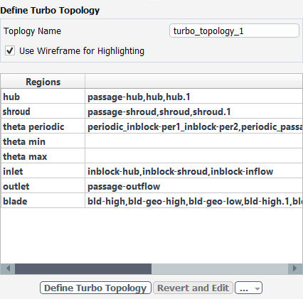
Specify a Topology Name, or keep the default value.
By default, the Use Wireframe for Highlighting option is selected so that the imported geometries are displayed in wireframe. Arrows are also used to indicate flow direction.
Use the table to review and/or assign topological zones to the list of regions provided. This table gives you an overall list of your simulation's regions and the zones assigned to them.
Once your selections are made, click the Define Turbo Topology button and proceed to the next task.
A separate child task will be created that shows the details of the particular turbo topology. Additional topologies can also be created using this task.
If you need to make adjustments to any of your settings in this task, click Revert and Edit, make your changes and click Update, or click Cancel to cancel your changes.
Proceed to the next step in the workflow.
Use the Define Turbo Surfaces task to create turbo surfaces at span-wise locations that will be used in solution post processing. You can define three surfaces by default, but you can create as many or as few as you need.
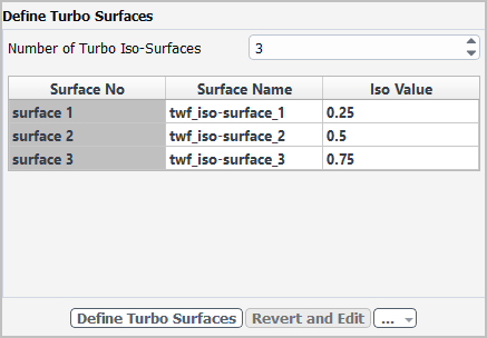
Specify the Number of Turbo Iso-Surfaces, or keep the default value of
3.Specify an Iso-Value for surface 1, or keep the default value of
0.25.Specify an Iso-Value for surface 2, or keep the default value of
0.5.Specify an Iso-Value for surface 3, or keep the default value of
0.75.Repeat as needed, depending on the number of iso-surfaces.
Click the Define Turbo Surfaces button to generate a list of turbo surfaces.
If you need to make adjustments to any of your settings in this task, click Revert and Edit, make your changes and click Update, or click Cancel to cancel your changes.
Proceed to the next step in the workflow.
Use the Create Report Definitions and Monitors task to have the workflow automatically create turbomachinery-related performance parameters such as flow rate, pressure-ratio, efficiency, and so on. In addition, you can use this task to have the workflow create contours for any iso-surfaces you created in the Define Turbo Surfaces task.
Determine whether or not you want contour plots to be automatically created for the surfaces you defined in the Define Turbo Surfaces task.
Click the Create button to generate the contour plots, if any, and a list of turbomachinery-related report definitions and monitors.
If you need to make adjustments to any of your settings in this task, click Revert and Edit, make your changes and click Update, or click Cancel to cancel your changes.
Once the workflow is completed, you can review various monitors and contours in the Outline View and you can proceed to run the turbo calculation.
In addition, you can make use of simulation reports within Ansys Fluent to further enhance your turbomachinery analysis. See Using Simulation Reports for details.
Commands related to using the Turbo Workflow through the text
command interface can be found in turbo-workflow/
When a task is complete and up-to-date, all controls within that task are disabled. If you need to make any changes to any of your settings within the task, enable the task's controls by clicking the Edit button within the task (or click Edit in the context menu from the workflow tree). Once you have made your changes, clicking Update restores the task's state (causing all subsequent up-to-date tasks to then become out-of-date) and updates the current task with its new changes. Downstream tasks will remain out-of-date until you update them manually. If you decide to select Cancel, then all changes are discarded and the task's state will remain up-to-date.
Some tasks include zone or label selection lists where you have made a selection. To edit such tasks, enable the task's controls by clicking the Revert and Edit button (or click Revert and Edit in the context menu), thereby reverting to the task's previous state, and causing all subsequent up-to-date tasks to then become out-of-date. Once you have made your changes, clicking Update then updates the current task with its new values. If you decide to select Cancel, then all changes are discarded and the task's state is not restored. The current task and all downstream tasks will remain out-of-date until you update them manually.
Some tasks include one or more fields whose label includes unit information, such that, from an already completed workflow session, you can return to the beginning of the workflow, change the unit designation and update all subsequent tasks, and the numerical values will be automatically updated corresponding to the new unit settings.
As you progress through using workflows, you can save them at any time using the
Save Workflow button (![]() ). When you save the workflow itself,
you save the tasks, sub-tasks, and their settings, as your own custom workflow template for
future use. You can also load any saved workflow using the Load
Workflow button (
). When you save the workflow itself,
you save the tasks, sub-tasks, and their settings, as your own custom workflow template for
future use. You can also load any saved workflow using the Load
Workflow button (![]() ). If you make a mistake in setting up
your workflow, you can delete the task (using the Delete command in the
context menu for the selected task), or even reset the entire workflow (using the
Reset Workflow button (
). If you make a mistake in setting up
your workflow, you can delete the task (using the Delete command in the
context menu for the selected task), or even reset the entire workflow (using the
Reset Workflow button (![]() )).
)).
It should be noted that when you write the mesh file (File > Write > Mesh...), Fluent saves the current workflow along with any mesh information within the saved mesh file.
While saving the mesh file, Fluent also locally copies relevant task editing data from
the current workflow session's temporary folder into a separate workflow-specific folder
(called, for example, my_mesh_file
_workflow_files). This workflow-specific folder contains task
editing data, making it easier to use the workflow when reverting and editing tasks, in
another Fluent session. Use the corresponding Save task editing data with mesh
file preference to enable or disable this behavior (see Applying Preferences to the Turbo Workflow for more information).
Note: Workflows are saved as workflow template files (using the
*.wft file extension). The *.wft files
include the version number of the current release (for example, for the
2024 R2, release, the files are internally designated with
"version": "24.2".
Additionally, all default settings in the workflow files or journals are model-based, therefore, default settings will change when the workflow file(s) are applied to a new model. If, however, you have explicitly changed any setting values, then those changes will be preserved as user settings across various models.
You can access global preferences for the Turbo Workflow in Fluent through the Preferences dialog, under the category.
![]() File → Preferences...
File → Preferences...
The following categories/preferences are most useful and applicable when using the Turbo Workflow:
General category:
When the Dockable Workflow Editor preference is enabled, and a new session started, a task's properties can be separated into the Workflow Editor, that can then be relocated (undocked) and resized elsewhere in the interface. This is especially useful for workflows with many tasks and/or an abundance of properties in one or more tasks..
You can relocate the Workflow Editor from its default location to any location in the Fluent interface. To return the editor to its default location, use the Default view from the list of view options.
Turbo Workflow category
Use the Save task editing data with case file option to ensure that workflow-specific task editing data is saved when you save the case file. This data will be saved in a corresponding workflow-specific folder alongside the case file (see Saving and Loading Turbo Workflows for more information). When this option is enabled, the Saving data for editing tasks preference is automatically set to Write case files.
For Saving data for editing tasks, you can determine how case files are managed when you edit your workflow tasks. Choices include:
Use the Write case files option to save a case file into a temporary folder while editing case-related tasks within the workflow.
When this option is enabled (the default), Fluent creates a case file for use when a completed case-related task must be edited.
When this option is disabled, Fluent will not create a case file, and when the completed case-related task must be edited, Fluent automatically updates each previous task in order to generate the required case file.
Disabling this preference is recommended if you do not need to edit your workflow tasks once they have been defined.
Use Do not save data to not save a case file while editing a task.
Note: If the Saving data for editing tasks option is set to Do not save data, and you are reverting any changes to a particular task, then updating that task subsequently updates all previous tasks.
Whether the Saving data for editing tasks option is set to Write case files, case information is saved for a particular task when the task is completed. When you choose to edit any settings to a completed task, the saved case information corresponding to that task is retrieved and the task's settings are restored accordingly.
See Editing Tasks in the Turbo Workflow for more information about reverting and updating tasks.