


The procedure for setting up a solidification/melting problem is described below. (Note that this procedure includes only those steps necessary for the solidification/melting model itself; you will need to set up other models, boundary conditions, and so on, as usual.)
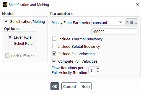
To use the solidification/melting model, enable the Solidification/Melting option in the Solidification and Melting dialog box (Figure 27.1: The Solidification and Melting Dialog Box).
 Setup → Models → Solidification & Melting
  Edit...
Ansys Fluent will automatically enable the energy equation, so you do not have to visit the Energy dialog box before turning on the solidification/melting model.
Under Parameters, specify the value of the Mushy Zone Parameter (
 in Equation 15–6) as a constant, or as a user-defined function. Refer to
 DEFINE_SOLIDIFICATION_PARAMSin the Fluent Customization Manual for detailed information about the user-defined function.Values between
 and
and  are recommended for most computations. The higher
the value of the Mushy Zone Parameter, the steeper
the damping curve becomes, and the faster the velocity drops to zero
as the material solidifies. Very large values may cause the solution
to oscillate as control volumes alternately solidify and melt with
minor perturbations in liquid volume fraction.
are recommended for most computations. The higher
the value of the Mushy Zone Parameter, the steeper
the damping curve becomes, and the faster the velocity drops to zero
as the material solidifies. Very large values may cause the solution
to oscillate as control volumes alternately solidify and melt with
minor perturbations in liquid volume fraction.If you want to include the pull velocity in your simulation (as described in Momentum Equations and Pull Velocity for Continuous Casting in the Theory Guide), enable the Include Pull Velocities option under Parameters.
If you are including pull velocities and you want Ansys Fluent to compute them (using Equation 15–22) based on the specified velocity boundary conditions, as described in Pull Velocity for Continuous Casting in the Theory Guide, enable the Compute Pull Velocities option and specify the number of Flow Iterations Per Pull Velocity Iteration.
Important: It is not necessary to have Ansys Fluent compute the pull velocities. See Procedures for Modeling Continuous Casting for information about other approaches.
The default value of 1 for the Flow Iterations Per Pull Velocity Iteration indicates that the pull velocity equations will be solved after each iteration of the solver. If you increase this value, the pull velocity equations will be solved less frequently. You may want to increase the number of Flow Iterations Per Pull Velocity Iteration if the liquid fraction equation is almost converged (that is, the position of the liquid-solid interface is not changing very much). This will speed up the calculation, although the residuals may jump when the pull velocities are updated.
Under Options, select either Lever Rule or Scheil Rule. See Species Equations in the Theory Guide for details.
Important: The Lever Rule and Scheil Rule options are available only when Species Transport is enabled in the Species Model dialog box.
If you select Scheil Rule, then you can enable Back Diffusion. Enter either a constant or a user-defined function to specify the value of the Back Diffusion Parameter (
 in Equation 15–19). Refer to
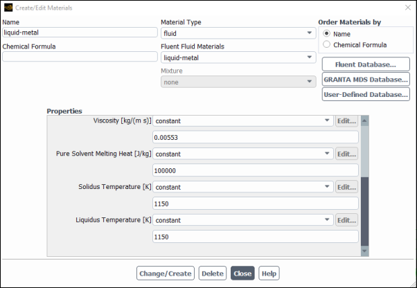
 DEFINE_SOLIDIFICATION_PARAMSin the Fluent Customization Manual for detailed information about the user-defined function. Note that the value for the Back Diffusion Parameter must be between 0 and 1.In the Create/Edit Materials Dialog Box (Figure 27.2: The Create/Edit Materials Dialog Box for Melting and Solidification), specify the Pure Solvent Melting Heat (
 in Equation 15–4), Solidus
Temperature (
in Equation 15–4), Solidus
Temperature ( in Equation 15–3),
and Liquidus Temperature (
in Equation 15–3),
and Liquidus Temperature ( in Equation 15–3) for the material being
used in your model. Setup →
in Equation 15–3) for the material being
used in your model. Setup →  Materials
Important: For solidification to occur, Pure Solvent Melting Heat must be set to a positive non-zero value.
If you are solving for species transport, you need to specify properties for the mixture, including the method by which the Solidus Temperature and the Liquidus Temperature are calculated. The default method is the mixing-law (Equation 15–8 and Equation 15–9 in the Theory Guide), in which the solidus temperature and the liquidus temperature are calculated from the parameters provided for each solute (such as the slope of the liquidus line or partition coefficient). However, a user-defined function of type
DEFINE_PROPERTYcan be used to specify both of these temperatures. See the Fluent Customization Manual for examples ofDEFINE_PROPERTY.Important: It is highly recommended that you use the same method for specifying the Solidus Temperature and the Liquidus Temperature.
When defining the mixture, you will also specify the Mass Diffusivity (
 in Equation 15–15 and Equation 15–18) and the Eutectic Temperature (
 in Equation 15–10), as well
as the Pure Solvent Melting Heat (
in Equation 15–10), as well
as the Pure Solvent Melting Heat ( in Equation 15–4) and the Pure Solvent Melting Temperature (
 in Equation 15–8 and Equation 15–9).
Note that the solvent is the last species listed under Selected
Species in the Species dialog box.
in Equation 15–8 and Equation 15–9).
Note that the solvent is the last species listed under Selected
Species in the Species dialog box.For each solute, you have to specify the Slope of Liquidus Line (
 in Equation 15–8 and Equation 15–9 in
the Theory Guide) with respect to the concentration of the solute, the Partition Coefficient (
in Equation 15–8 and Equation 15–9 in
the Theory Guide) with respect to the concentration of the solute, the Partition Coefficient ( in Equation 15–8),
the Eutectic Mass Fraction (
in Equation 15–8),
the Eutectic Mass Fraction ( in Equation 15–10), and, if Lever Rule is selected in the Solidification and Melting dialog box, the coefficient for Diffusion in Solid (
 in Equation 15–15). It is not necessary to specify
  ,
,  ,
,  , and
, and  for the solvent.
Set the boundary conditions.
Setup → Boundary Conditions
In addition to the usual boundary conditions, consider the following:
If you want to account for the presence of an air gap between a wall and an adjacent solidified region (as described in Contact Resistance at Walls in the Theory Guide), specify a nonzero value, a profile, or a user-defined function for Contact Resistance (
 in Equation 15–23) under Thermal Conditions in the Wall Dialog Box.
If you want to specify the gradient of the surface tension with respect to the temperature at a wall boundary, you can use the Marangoni Stress option for the wall Shear Condition. See Marangoni Stress for details.
If you want Ansys Fluent to compute the pull velocities during the calculation, note how your specified velocity conditions are used in this calculation (see Pull Velocity for Continuous Casting in the Theory Guide).
Procedures for Modeling Continuous Casting contains additional information about modeling continuous casting. See Solution Procedure and Postprocessing for information about solving a solidification/melting model and postprocessing the results.