


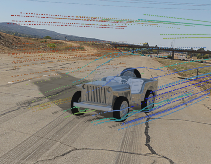
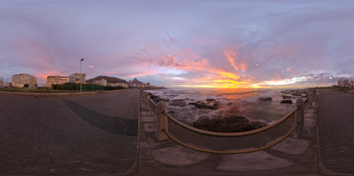
You can perform realistic rendering of your model using raytracing, as shown in Figure 40.77: Example of Realistic Rendering on a Highway Midday.
To create a realistic raytracing display:
Display the graphics object that you want to render with raytracing. Mesh objects allow you to color your model with realistic materials that look especially good in the raytracing display. See Realistic Rendering of Materials for additional information.
Open the Raytracing Display dialog box.
 View →
Graphics → Raytracing
Display...
View →
Graphics → Raytracing
Display...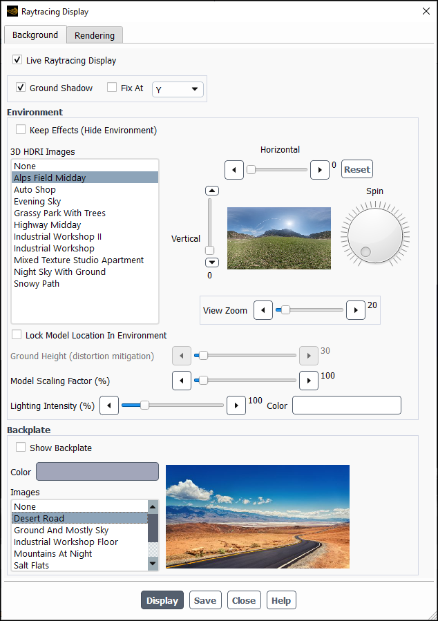
(Optional) Enable Live Raytracing Display to make it so that changes made to controls in the Background tab are immediately reflected in the raytracing window (which is only seen after you click ).
(Optional) Enable Ground Shadow to have the displayed object cast shadows on the environment based on the defined lights and environment lighting.
With the Ground Shadow enabled, you can also choose to lock the location of that shadow onto a plane by enabling Fix At and selecting the desired axis from the drop-down list. For example, if you have a model that is defined such that +Z represents the "up" direction, you would want to lock the shadow at Z.
Note: You may want to define additional lights (Defining Light Sources) to make the shadow(s) more apparent.
(Optional) Enable Keep Effects (Hide Environment) to keep the effects of the selected environment (such as lighting and reflections) without displaying the environment.
Select the environment you want displayed with your model from the 3D HDRI Images list. Refer to Listing of Realistic Environments and Backplates for more information on the available environments.
Determine if you want to display your model in a 3D environment or if you just want a backplate as the background behind your model. If you want lighting effects on your model, you must pick an environment. You can then decide whether you also want one of the available backplates behind your model. Options for backplates include colors as well as a few different images.
Modify the environment properties to suit your requirements:
Adjust the orientation and appearance of the environment with respect to your model, using the Vertical, Horizontal, and Spin controls. These controls operate based on the point of view of the graphics window. Since these controls are based on the current view, rather than a fixed XYZ origin, they may not ensure a consistent appearance even when the same values are used.
Adjust the field of view using the View Zoom slider, which adjusts how much of the 3D environment is shown in the graphics window. You can resize the model as needed to match the environment using the Model Scaling Factor slider.
Fine tune the relationship between the displayed object and the environment. Enable Lock Model Location in Environment to "fix" the location of the displayed object so that as the model is rotated, its position does not change within the environment. Locking the model in the environment may result in some distortion, which can be minimized by adjusting the height of the environment ground using the Ground Height (distortion mitigation) slider.
Adjust the lighting Intensity and Color using the slider control and color picker.
(Optional) Enable Show Backplate to use a color or static image as the background to the raytracing display.
Select either a color or an Image for the backplate.
Click to render the raytracer image. Clicking Save retains the settings shown in the Raytracing Display dialog box without the need to display the image. This allows you to control the settings for saving raytracer images without displaying first.
(Optional) Specify the rendering options:
Click Rendering to open the Rendering tab, which contains options for controlling the quality of the raytracer image.
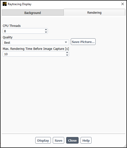
(Advanced) Set the number of CPU Threads that you want used for the raytracing computations. Note that if specify a number of threads that is greater than the number of cores available on your machine, the raytracer will use the maximum number of available cores.
Specify the Quality of image you want displayed and/or saved when you save the display using the Save Picture dialog box. Higher quality displays take longer to render.
Specify how long you want to spend rendering a raytracing image before Fluent captures it and saves it to a file.
Click or .
Important: The Raytracing window is not interactive, so the orientation, zoom, and location of the model (and 3D environment, if applicable) is controlled in the user-window that was active when you clicked Display in the Raytracing Display dialog box.
There are two approaches for creating realistic solution animations, as discussed in the following sections:
In either case, the animation definition must be created prior to calculating the solution for any results you want included in the animation.
While you are setting up your animation definition (as described in Animating the Solution) you have the option save raytracer images as the solution is iterating.
To directly save raytracer images:
Create and display the desired graphics object (contours, vectors, pathlines, particle tracks, or scenes).
Create an animation definition for this graphics object that includes enabling the Raytracer Image option. Note that raytracer images can only be saved in 2D image formats, such as PNG or JPEG. Refer to Animating the Solution for additional information on creating animation definitions.
 Solution
→ Calculation Activities
Solution
→ Calculation Activities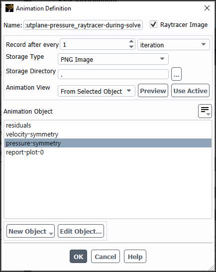
Open the Raytracing Display dialog box and select the desired environment and/or backplate and update the display to the desired appearance.
View →
Graphics → Raytracing
Display...Click Save Picture... in the Rendering tab to open the Save Picture dialog box.
Ensure settings like Resolution match your expectations, because this will control the size of the images saved for creating the animation. Click Apply to retain the desired settings.
Instead of saving raytracer images directly while the solver is iterating (as described in Realistic Raytracer Images Captured at Runtime), you can save HSF animation files during the solver run, and convert them to raytracer images afterwards, using the Playback dialog box. The appeal of this option is that it is more expensive to save raytracer images, so if they are being saved during the solver run, it can take longer (clock time) for the solver to converge. Converting your animation to use better, raytracer images after the solver run gives you the flexibility to use alternative computing resources to attain your desired video quality and appearance.
To create raytracing animations during postprocessing:
Ensure your animation images are saved in HSF format by confirming that HSF File is selected for Storage Type in the Animation Definition dialog box.
Open the Playback dialog box and read or select the desired Animation Sequence.
Results
→ Animations
→ Playback Edit
Edit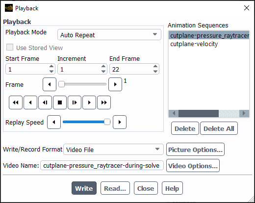
Click Picture Options... to open the Save Picture dialog box.
Enable Raytracer Image.
Set the desired Format and Resolution and click , then the Save Picture dialog box.
Open the Raytracing Display dialog box.
View →
Graphics → Raytracing
Display...Specify the desired settings, including environment, backplate, and rendering options.
Click , then . Alternatively, if you know your desired settings and do not need to make further changes after seeing the raytracing display, you can just click to avoid rendering the display, saving time.
Provide a Video Name and click to save the raytracer animation. Clicking Video Options... allows you to review additional video settings, such as frames per second (fps) and the video file format.
Important: When converting an HSF animation to a raytracer animation, you can change:
Lighting, including adding and removing lights (Adding Lights)
Camera orientation (Controlling the Display State and Modifying the View)
Any settings available in the Raytracing Display dialog box
You cannot change the material (Realistic Rendering of Materials) used in rendering your model.
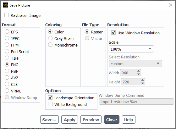
There are two ways that you can save raytracer images using the Save Picture dialog box. The type of image you want determines the approach you use.
Open the Save Picture dialog box.
![]() File → Save
Picture...
File → Save
Picture...
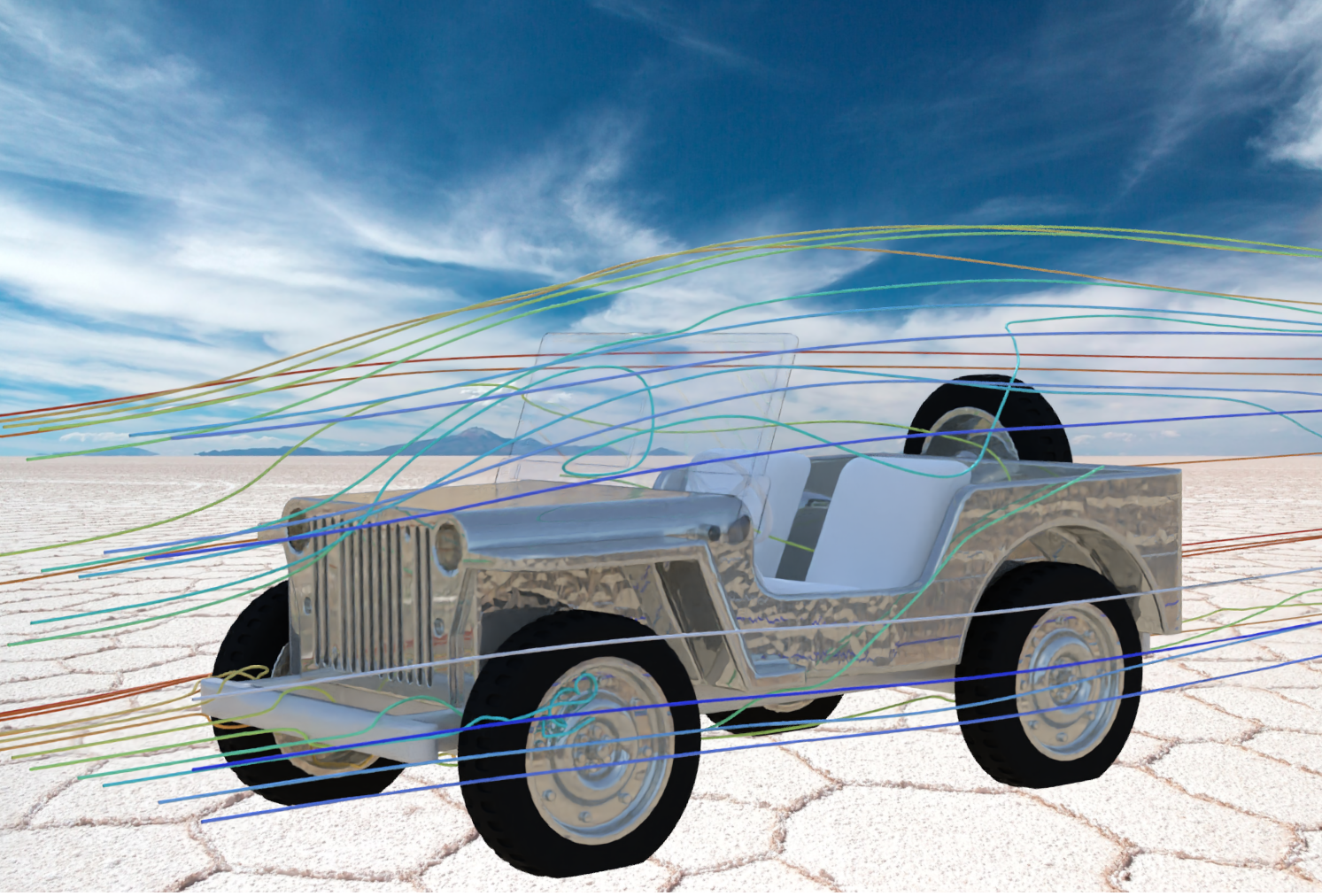
Enable the Raytracer Image option if you want to save an image likeFigure 40.78: Raytracer Scene Display with Backplate.
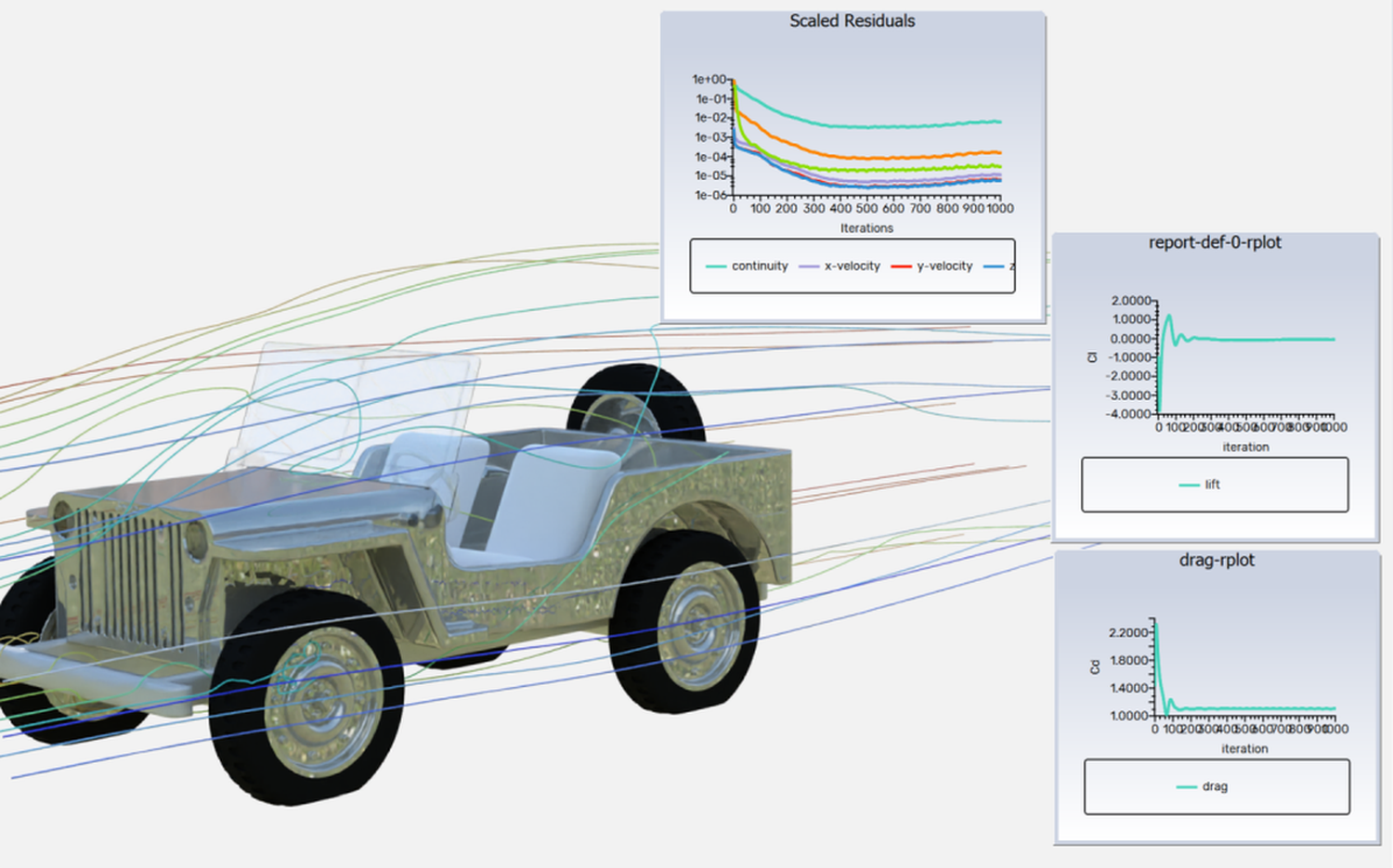
Disable the Raytracer Image option if you want to save an image like Figure 40.79: Raytracer Scene Display with Embedded Plots, which is setup as an embedded window dashboard (Embedded Graphics Window Dashboards).
To create and capture this type of image:
Display the desired object that you want raytraced. This can be a mesh, contours, vectors, pathlines, particle tracks, LIC, or scene plot.
Open the Raytracing Display dialog box, specify the desired settings, and click .
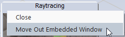
Right-click the title bar of the raytracing window and select Move Out Embedded Window.
Display the 2D plots (or any other graphics display such as contours or vectors) you want to embed in the raytracing window. Ensure each plot or object is opened in a new window.
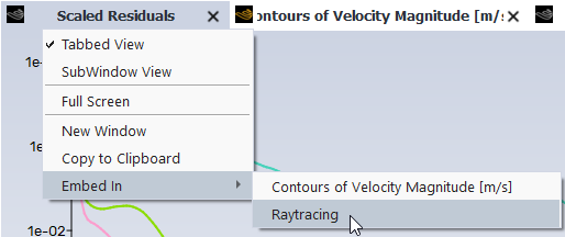
Right-click each 2D plot title bar and pick Embed in > Raytracing.
Click on the raytracing window to make it active, then open the Save Picture dialog box.
Ensure the Raytracer Image option is disabled. Specify the other desired settings and click .
Important: The Raytracing window will be saved at the same dimensions as the current window resolution. Disabling Use Window Resolution and specifying an alternative resolution will only change the scaling of the other embedded windows (the plot windows).
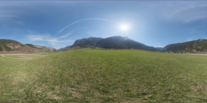
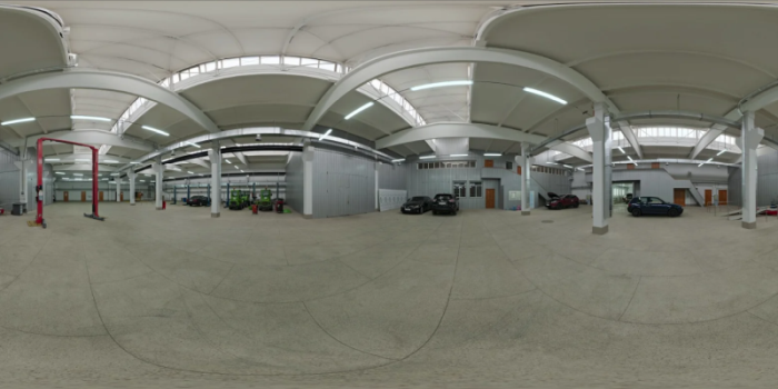
The following is a listing of the available realistic environments.
Alps Field Midday
Auto Shop
Evening Sky
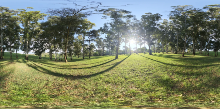
Grassy park with Trees
Highway Midday
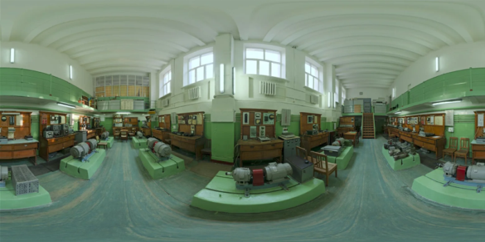
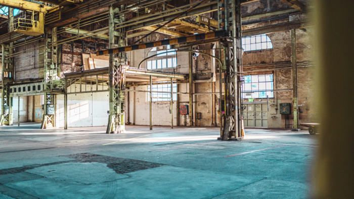
Industrial Workshop II
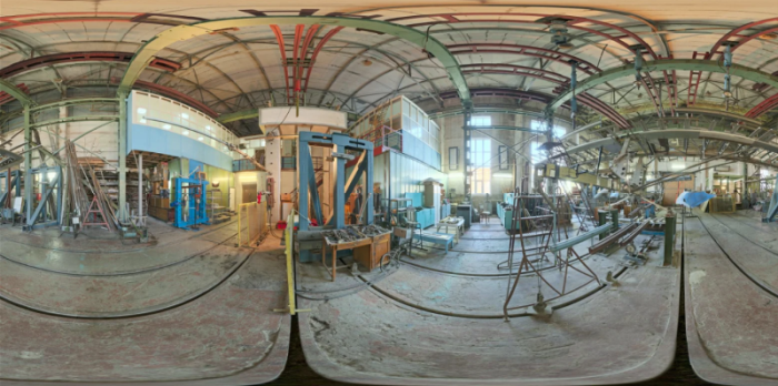
Industrial Workshop
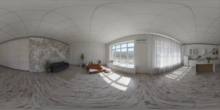
Mixed Texture Studio Apartment
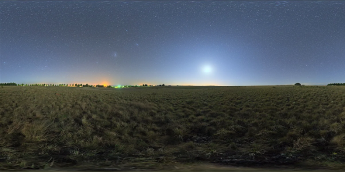
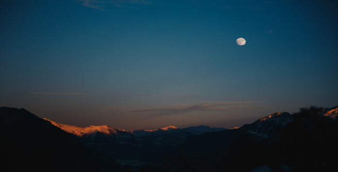
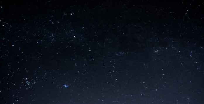
Night Sky with Ground
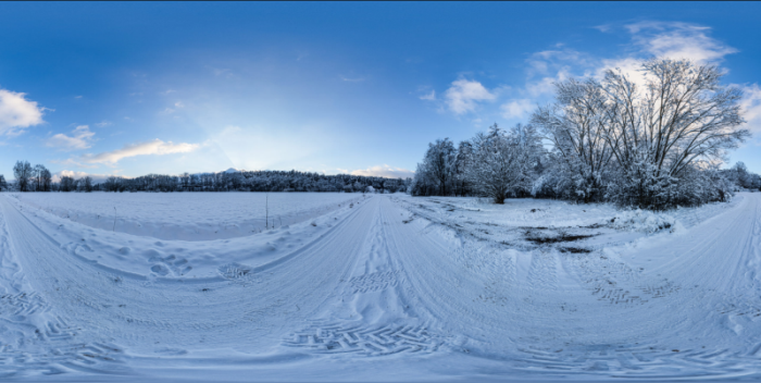
Snowy Path
The following is a list of the available backplate images:
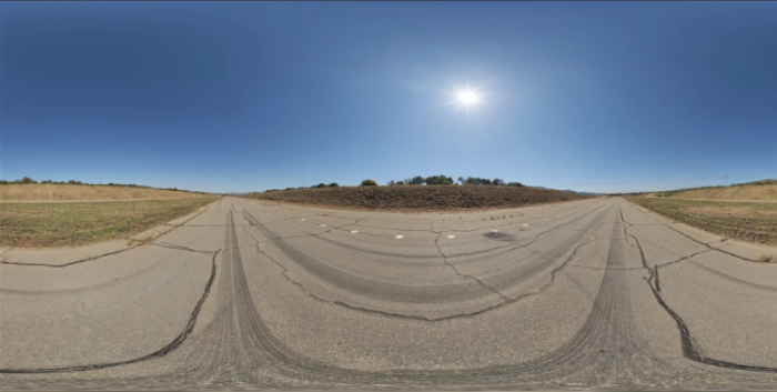
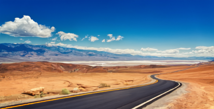
Desert Road
Ground and Mostly Sky

Industrial Workshop Floor
Mountains at Night
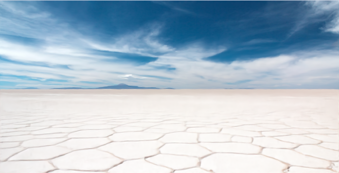
Salt Flats
Space
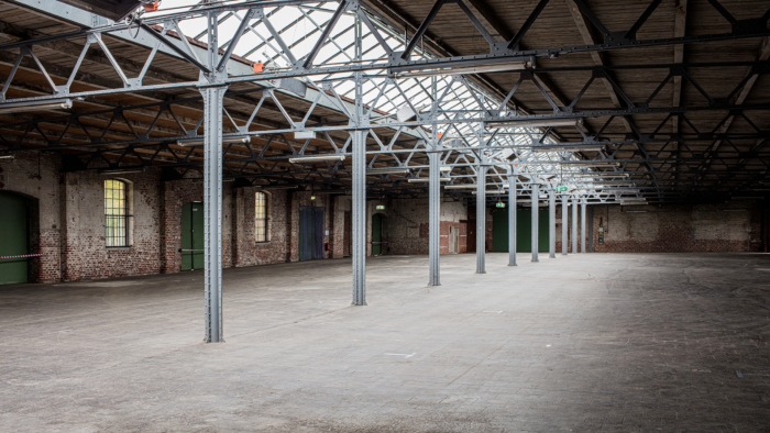
Warehouse with Skylights
Water and Mostly Sky

The limitations associated with realistic raytracing are listed below:
Embedded window dashboard objects containing a realistic raytracing display are not saved with the case file.
Realistic raytracing displays cannot be displayed in orthographic view, due to the nature of raytracing computations.
Realistic raytracing displays are incompatible with the Monochrome option in the Save Picture dialog box. If a raytracing display window is embedded in a regular graphics display (such as a mesh object), the Fluent window will be monochrome, but the raytracing window will be in color.
Realistic raytracing is only supported for graphics windows containing 3D surfaces. Windows only containing 2D displays, such as plots or animations (in 2D formats like PNG or JPG), cannot be raytraced.
Scene animations, also referred to as keyframe animations, are not compatible with raytracing displays.