The user-defined fan model in Ansys Fluent allows you to periodically regenerate a profile file that can be used to specify the characteristics of a fan, including pressure jump across the fan, and radial and swirling components of velocity generated by the fan.
For example, consider the calculation of the pressure jump across the fan. You can, through the standard interface, input a constant for the pressure jump, specify a polynomial that describes the pressure jump as a function of axial velocity through the fan, or use a profile file that describes the pressure jump as a function of the axial velocity or location at the fan face. If you use a profile file, the same profile will be used consistently throughout the course of the solution. Suppose, however, that you want to change the profile as the flow field develops. This would require a periodic update to the profile file itself, based upon some instructions that you supply. The user-defined fan model is designed to help you do this.
To use this model, you need to generate an executable that reads a fan profile file that is written by Ansys Fluent, and writes out a modified one, which Ansys Fluent will then read. The source code for this executable can be written in any programming language (Fortran or C, for example). Your program will be called and executed automatically, according to inputs that you supply through the standard interface.
Information about the user-defined fan model is provided in the following sections.
To make use of the user-defined fan model, follow the steps below.
In your model, identify one or more interior faces to represent one or more fan zones.
 Setup →
  Boundary Conditions
Input the name of your executable and the instructions for reading and writing profile files in the User-Defined Fan Model Dialog Box.
 User Defined → Model Specific → Fan
Model...
User Defined → Model Specific → Fan
Model...Initialize the flow field and the profile files.
Enter the fan parameters using the standard Fan Dialog Box (opened from the Boundary Conditions Task Page).
Perform the calculation.
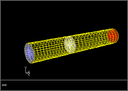
Usage of the user-defined fan model is best demonstrated by an example. With this in mind, consider the domain shown in Figure 7.91: The Inlet, Fan, and Pressure Outlet Zones for a Circular Fan Operating in a Cylindrical Domain. An inlet supplies air at 10 m/s to a cylindrical region, 1.25 m long and 0.2 m in diameter, surrounded by a symmetry boundary. At the center of the flow domain is a circular fan. A pressure outlet boundary is at the downstream end.
Figure 7.91: The Inlet, Fan, and Pressure Outlet Zones for a Circular Fan Operating in a Cylindrical Domain
Solving this problem with the user-defined fan model will cause Ansys Fluent to periodically write out a radial profile file with the current solution variables at the fan face. These variables (static pressure, pressure jump, axial, radial, and swirling (tangential) velocity components) will represent averaged quantities over annular sections of the fan. The sizes of the annular regions are determined by the size of the fan and the number of radial points to be used in the profiles.
Once the profile file is written, Ansys Fluent will invoke an executable, which will perform the following tasks:
Read the profile file containing the current flow conditions at the fan.
Perform a calculation to compute new values for the pressure jump, radial velocity, and swirl velocity for the fan.
Write a new profile file that contains the results of these calculations.
Ansys Fluent will then read the new profile file and continue with the calculation.
Specification of the parameters for the user-defined fan begins in the User-Defined Fan Model Dialog Box (Figure 7.92: The User-Defined Fan Model Dialog Box).
![]() User Defined → Model Specific → Fan
Model...
User Defined → Model Specific → Fan
Model...
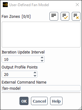
In this dialog box, you can select the fan zone(s) on which your executable will operate under Fan Zones. In this example, there is only one fan, fan-8. If you have multiple fan zones in a simulation, for which you have different profile specifications, you can select them all at this point. Your executable will be able to differentiate between the fan zones because the zone ID for each fan is included in the solution profile file. The executable will be invoked once for each zone, and separate profile files will be written for each.
The executable file will be called on to update the profile file periodically, based on the input for the Iteration
Update Interval. An input of 10, as shown in the dialog box, means that the fan executable in
this example will act every 10 iterations to modify the profile file.
The number of points in the profile file to be written by Ansys Fluent is entered under Output Profile Points. This profile file can have the same or a different number of points as the one that is written by the external executable.
Finally, the name of the executable should be entered under External Command Name. In the current example,
the name of the executable is fan-model.
Important: If the executable is not located in your working directory, then you must type the complete path to the executable.
The executable file will be built from the Fortran program, fantest.f, which is shown below.
 c
 c  This program is invoked at intervals by Ansys Fluent to
 c  read a profile-format file that contains radially
 c  averaged data at a fan face, compute new pressure-jump
 c  and swirl-velocity components, and write a new profile
 c  file that will subsequently be read by Ansys Fluent to
 c  update the fan conditions.
 c
 c  Usage: fantest input_profile output_profile
 c
   integer npmax
   parameter (npmax = 900)
   integer inp         ! input: number of profile points
   integer iptype      ! input: profile type (0=radial, 1=point)
   real ir(npmax)      ! input: radial positions
   real ip(npmax)      ! input: pressure
   real idp(npmax)     ! input: pressure-jump
   real iva(npmax)     ! input: axial velocity
   real ivr(npmax)     ! input: radial velocity
   real ivt(npmax)     ! input: tangential velocity
   character*80 zoneid
   integer rfanprof    ! function to read a profile file
   integer status
 c
   status = rfanprof(npmax,zoneid,iptype,
  $  inp,ir,ip,idp,iva,ivr,ivt)
   if (status.ne.0) then
     write(*,*) ’error reading input profile file’
   else
     do 10 i = 1, inp
       idp(i) = 200.0 - 10.0*iva(i)
       ivt(i) = 20.0*ir(i)
       ivr(i) = 0.0
  10  continue
   call wfanprof(6,zoneid,iptype,inp,ir,idp,ivr,ivt)
   endif
   stop
   end
After the variable declarations, which have comments on the right, the subroutine rfanprof is called to
read the profile file, and pass the current values of the relevant variables (as defined in the declaration list) to
fantest. A loop is done on the number of points in the profile to compute new values for:
The pressure jump across the fan,
idp, which in this example is a function of the axial velocity,iva.The swirling or tangential velocity,
ivt, which in this example is proportional to the radial position,ir.The radial velocity,
ivr, which in this example is set to zero.
After the loop, a new profile is written by the subroutine wfanprof, shown below. (For more information
on profile file formats, see Profile File Formats.)
  subroutine wfanprof(unit,zoneid,ptype,n,r,dp,vr,vt)
 c
 c  writes an Ansys Fluent profile file for input by the
 c  user fan model
 c
   integer unit       ! output unit number
   character*80 zoneid
   integer ptype      ! profile type (0=radial, 1=point)
   integer n          ! number of points
   real r(n)          ! radial position
   real dp(n)         ! pressure jump
   real vr(n)         ! radial velocity
   real vt(n)         ! tangential velocity
   character*6 typenam
   if (ptype.eq.0) then
     typenam = ’radial’
   else
     typenam = ’point’
   endif
   write(unit,*) ’((’, zoneid(1:index(zoneid,’\0’)-1), ’ ’,
  $  typenam, n, ’)’
   write(unit,*) ’(r’
   write(unit,100) r
   write(unit,*) ’)’
   write(unit,*) ’(pressure-jump’
   write(unit,100) dp
   write(unit,*) ’)’
   write(unit,*) ’(radial-velocity’
   write(unit,100) vr
   write(unit,*) ’)’
   write(unit,*) ’(tangential-velocity’
   write(unit,100) vt
   write(unit,*) ’)’
  100 format(5(e15.8,1x))
   return
   end
This subroutine will write a profile file in either radial or point format, based on your input for the integer
ptype. (See Profiles for more details on the types of profile files that are
available.) The names that you use for the various profiles are arbitrary. Once you have initialized the profile files, the names
you use in wfanprof will appear as profile names in the Fan Dialog Box.
The next step in the setup of the user-defined fan is to initialize (create) the profile files that will be used. To do this,
first initialize the flow field with the Solution Initialization Task Page (using the velocity inlet
conditions, for example), and then type the command (update-user-fans) in the console window. (The
parentheses are part of the command, and must be typed in.)
This will create the profile names that are given in the subroutine wfanprof.
Once the profile names have been established, you will need to visit the Fan Dialog Box (Figure 7.93: The Fan Dialog Box) to complete the problem setup. (See Fan Boundary Conditions for general information on using the Fan dialog box.)
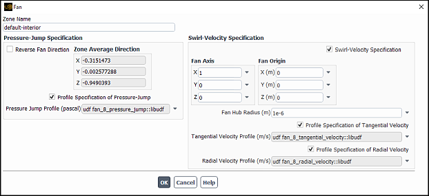
At this time, the Fan Axis, Fan Origin, and Fan Hub Radius can be
entered, along with the choice of profiles for the calculation of pressure jump, tangential velocity, and radial velocity. With
the profile options enabled, you can select the names of the profiles from the drop-down lists. In the dialog box above, the
selected profiles are named fan_8_pressure_jump, fan_8_tangential_velocity, and
fan_8_radial_velocity, corresponding to the names that were used in the subroutine
wfanprof.
The solution is now ready to run. As it begins to converge, the report in the console window shows that the profile files are being written and read every 10 iterations:
    iter   continuity   x-velocity   y-velocity   z-velocity          k
!      1   residual normalization factors changed (continuity
       1   1.0000e+00   1.0000e+00   1.0000e+00   1.0000e+00   1.0000e+00
!      2   residual normalization factors changed (continuity
       2   1.0000e+00   1.0000e+00   1.0000e+00   1.0000e+00   9.4933e-01
       3   6.8870e-01   7.2663e-01   7.3802e-01   7.5822e-01   6.1033e-01
       .       .           .              .           .            .
       .       .           .              .           .            .
       .       .           .              .           .            .
       9   2.1779e-01   9.8139e-02   3.0497e-01   2.9609e-01   2.8612e-01
 Writing "fan-8-out.prof"...
 Done.
 Reading "fan-8-in.prof"...

 Reading profile file...
      10   "fan-8"  radial-profile points, r, pressure-jump,
                           radial-velocity, tangential-velocity.

 Done.
      10   1.7612e-01   7.4618e-02   2.5194e-01   2.4538e-01   2.4569e-01
      11   1.6895e-01   8.3699e-02   2.0316e-01   2.0280e-01   2.1169e-01
       .       .           .              .           .            .
       .       .           .              .           .            .
       .       .           .              .           .            .
The file fan-8-out.prof is written out by Ansys Fluent and read by the executable
fantest. It contains values for pressure, pressure jump, axial velocity, radial velocity, and tangential
velocity at 20 radial locations at the site of the fan. The file fan-8-in.prof is generated by
fantest and contains updated values for pressure jump and radial and tangential velocity only. It is
therefore a smaller file than fan-8-out.prof. The prefix for these files takes its name from the fan zone
with which the profiles are associated. An example of the profile file fan-8-in.prof is shown below. This
represents the last profile file to be written by fantest during the convergence history.
 ((fan-8 radial 10)
 (r
 0.24295786E-01 0.33130988E-01 0.41966137E-01 0.50801374E-01 0.59636571E-01
 0.68471842E-01 0.77307090E-01 0.86142287E-01 0.94963484E-01 0.95353782E-01
 )
 (pressure-jump
 0.10182057E+03 0.98394081E+02 0.97748657E+02 0.97787750E+02 0.97905228E+02
 0.98020668E+02 0.98138817E+02 0.98264198E+02 0.98469681E+02 0.98478783E+02
 )
 (radial-velocity
 0.00000000E+00 0.00000000E+00 0.00000000E+00 0.00000000E+00 0.00000000E+00
 0.00000000E+00 0.00000000E+00 0.00000000E+00 0.00000000E+00 0.00000000E+00
 )
 (tangential-velocity
 0.48591572E+00 0.66261977E+00 0.83932275E+00 0.10160275E+01 0.11927314E+01
 0.13694369E+01 0.15461419E+01 0.17228458E+01 0.18992697E+01 0.19070756E+01
 )
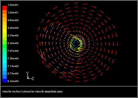
A plot of the transverse velocity components at the site of the fan is shown in Figure 7.94: Transverse Velocities at the Site of the Fan. As expected, there is no radial component, and the tangential (swirling) component increases with radius.
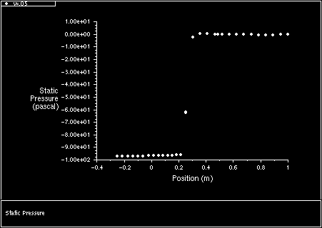
As a final check on the result, an XY plot of the static pressure as a function of  position is shown (Figure 7.95: Static Pressure Jump Across the Fan). This XY plot is made on a line at
 =0.05 m, or at about half the radius of the duct. According to the input file shown above, the pressure jump at
the site of the fan should be approximately 97.8 Pa/m. Examination of the figure supports this finding.
=0.05 m, or at about half the radius of the duct. According to the input file shown above, the pressure jump at
the site of the fan should be approximately 97.8 Pa/m. Examination of the figure supports this finding.