General Information About Using the Solution Controls Dialog Box
You can use the Solution Controls dialog box if you are performing a static or full transient analysis.
The Solution Controls dialog box consists of five tabbed "pages," each of which contains a set of related solution controls. The tabs, in order from left to right, include:
Each set of controls is logically grouped on a tab; the most basic controls appear on the first tab, with each subsequent tab providing more advanced controls. The Transient tab contains transient analysis controls; it is available only when you choose a transient analysis and remains grayed out when you choose a static analysis.
Once you are satisfied with the settings on the Basic tab, you do not need to progress through the remaining tabs unless you want to change some of the advanced controls. As soon as you click on any tab of the dialog box, the settings are applied to the database and the dialog box closes.
Note: Whether you make changes to only one or to multiple tabbed pages, your changes are applied to the database only when you click to close the dialog box.
Basic Tab
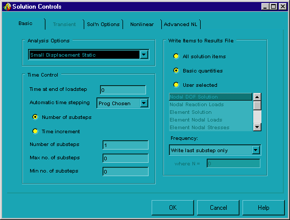
Use the Basic tab to specify the options described below. The controls that appear on the Basic tab provide the minimum amount of data that the program needs for the analysis.
- Analysis Options
[ANTYPE, NLGEOM]--Specifies the type of analysis that you want to perform. (The "large deformation effects" referred to below include large deflection, large rotation, and/or large strain, depending on the element type being used.) You can choose one of these options:
Small Displacement Static: Performs a linear static analysis (that is, a static analysis in which large deformation effects are ignored).
Large Displacement Static: Performs a nonlinear static analysis (that is, a static analysis in which large deformation effects are included).
Small Displacement Transient: Performs a linear full transient analysis (that is, a full transient analysis in which large deformation effects are ignored).
Large Displacement Transient: Performs a nonlinear full transient analysis (that is, a full transient analysis in which large deformation effects are included).
Restart Current Analysis: Restarts the current analysis.
- Time Control
Controls various time settings.
In the Time at end of loadstep [TIME] entry box, specify a time value for Mechanical APDL to associate with the boundary conditions at the end of the load step.
Click the Automatic time stepping [AUTOTS] drop down list box to turn automatic time stepping on, off, or have Mechanical APDL automatically switch it on and off between substeps of a load step as needed.
Determine how you want to control the number of substeps that are taken within a load step. You can choose either Number of substeps or Time increment:
Number of substeps [NSUBST]: Indicates that you want to specify a specific number of substeps to be taken within this load step. If you choose this option, you can use the Number of substeps, Max no. of substeps, and Min no. of substeps entry boxes to specify starting values and limits for substeps. How these limits are interpreted by Mechanical APDL depends on what option you selected in the Automatic time stepping drop down list box:
Number of substeps: If automatic time stepping is turned off, specifies the number of substeps to be taken this load step (that is, the time step size or frequency increment). If automatic time stepping is turned on, specifies the size of the first substep.
Max no. of substeps: Specifies the maximum number of substeps to be taken (that is, the minimum time step size) if automatic time stepping is turned on.
Min no. of substeps: Specifies the minimum number of substeps to be taken (that is, the maximum time step size) if automatic time stepping is turned on.
Time increment [DELTIM]: Indicates that you want to specify the time step size for this load step. If you choose this option, you can use the Time step size, Minimum time step, and Maximum time step entry boxes to specify starting values and limits for time steps. How these limits are interpreted by Mechanical APDL depends on what option you selected in the Automatic time stepping drop down list box:
Time step size: If automatic time stepping is turned off, specifies the time step size for this load step. If automatic time stepping is turned on, specifies the starting time substep.
Minimum time step: Specifies the minimum time step size (if automatic time stepping is turned on).
Maximum time step: Specifies the maximum time step size (if automatic time stepping is turned on).
- Write Items to Results File
[OUTRES]--Specifies the solution data that you want Mechanical APDL to write to the results file (database). You can choose one of these options:
All solution items: Writes all solution items to the database.
Basic quantities: Writes only the following solution items to the database: nodal DOF solution; nodal reaction loads; element nodal loads and input constraint and force loads; element nodal stresses; element nodal gradients; and element nodal fluxes.
User selected: Writes only selected solution items. If you select this option, use the list box to choose the specific solution items that you want Mechanical APDL to write to the database. Ctrl-click on each item to select it; to unselect a selected item, Ctrl-click on it again.
Use the Frequency drop down list box to indicate how frequently you want Mechanical APDL to write the selected solution items to the database. You can choose one of these options: Write every substep, Do not write any substeps, Write last substep only, Write every Nth substep, or Write N number of substeps.
For more information about the controls on the Basic tab, see Loading and The General Postprocessor (POST1) in the Basic Analysis Guide.
Transient Tab
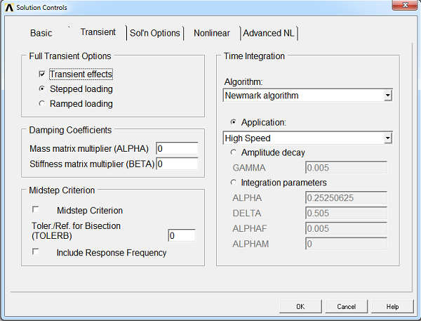
Use the Transient tab to specify the options described below.
- Full Transient Options
Specifies the transient options that you want to include in the analysis. You can set one or more of these options:
Transient effects [TIMINT]: Includes transient effects (for example, structural inertia).
Stepped loading/Ramped loading [KBC]: Choose between stepped loading or ramped loading by clicking the desired button. When loading is stepped, loads are step changed at the first substep of this load step to the values of this load step (that is, the same values are used for all substeps). When loading is ramped, loads are linearly interpolated for each substep from the values of the previous load step to the values of this load step.
- Damping Coefficients
Specifies various damping options. One form of the viscous damping matrix [C] is given by α[M] + β[K], where [M] is the mass matrix and [K] is the stiffness matrix. You can specify values for one or both of the following:
- Midstep Criterion
Specifies the midstep residual criterion to be used in the analysis [MIDTOL command]:
Midstep Criterion: Activate midstep residual criterion.
Tol/Ref for Bisection: Midstep residual tolerance (if > 0) or reference value (if < 0) used for bisection.
Include Response Frequency: Calculate response frequency and consider it in the automatic time stepping.
- Time Integration
Specifies time integration method and parameters.
Algorithm [TRNOPT]: Choose the Newmark algorithm or the HHT algorithm.
Integration parameters [TINTP] can be set by choosing one of these options:
Application: Choose an application type: High Speed, Impact, Moderate Speed, Low Speed, or Quasi-Static. Many transient dynamic analysis settings can be automatically set by the program based on the intended application. For more information, see Transient Dynamic Analysis Settings Based on Application in the Structural Analysis Guide.
Amplitude decay: Defines an amplitude decay for the second order transient integration. If you choose this option, use the GAMMA entry box to specify the factor.
Integration parameters: Allows individual input of each integration parameter. If you choose this option, use the ALPHA and DELTA entry boxes to specify the Newmark parameters. If the HHT algorithm was selected, use ALPHAM and ALPHAF to specify additional HHT parameters.
For more information about the controls on the Transient tab, see Transient Dynamic Analysis.
Sol'n Options Tab
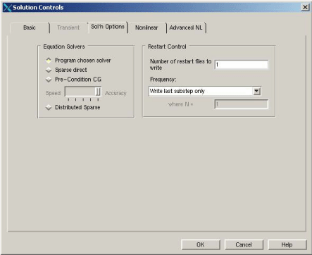
Use the Sol'n Options tab to specify the options described below.
- Equation Solvers
[EQSLV]--Specifies the type of equation solver that you want to use. You can choose one of these options:
Program chosen solver: Mechanical APDL selects a solver for you, based on the physics of the problem.
Sparse direct: This direct elimination solver is suited for analyses in which robustness and solution speed are required (nonlinear analyses), and for linear analyses in which iterative solvers are slow to converge (especially for ill-conditioned matrices, such as poorly shaped elements). Memory use is medium; disk use is high.
Pre-Condition CG: This iterative solver is suited for analyses in which solution speed is crucial, such as in linear analyses of large models. Especially well suited for bulky structures modeled with solid elements. Memory use is medium; disk use is low. If you choose this option, use the slider to set the accuracy level for convergence for the solver. The accuracy level can vary from 1 (fastest setting, fewer number of iterations) to 5 (slowest setting, accurate, more number of iterations).
For detailed information on these solvers, see the Basic Analysis Guide.
- Restart Control
[RESCONTROL]--Restarts an analysis from any point. In the Number of restart files to write entry box, indicate the maximum number of restart files that you want Mechanical APDL to write for a load step.
Click the Frequency drop down list box and choose how frequently you want restart files to be written to the database. You can choose one of these options: Write every substep, Do not write any files, Write last substep only, Write every Nth substep, or Write N number of substeps.
For more information about the controls on the Sol'n Options tab, see Solution in the Basic Analysis Guide.
Nonlinear Tab
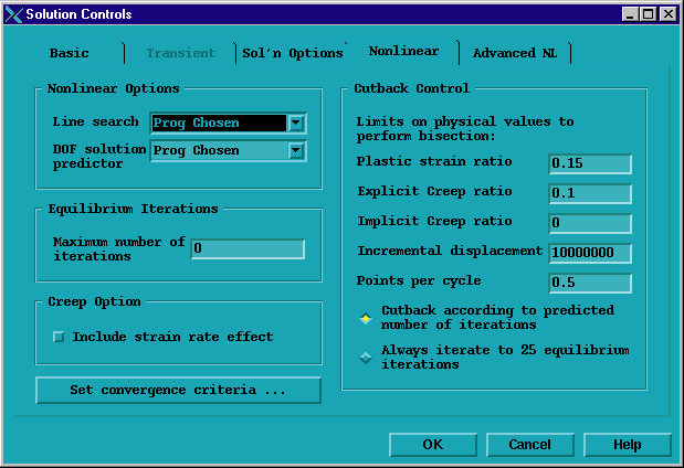
Use the Nonlinear tab to specify the options described below.
- Nonlinear Options
Controls several nonlinear options and how they are used in the analysis. You can set one or both of these options:
Line search [LNSRCH]: Activates a line search to be used with the Newton-Raphson method. Line search is an alternative to adaptive descent. You can turn line search on or off, or have Mechanical APDL automatically switch line searching on and off between substeps of a load step as needed. This setting, which is recommended, can be very efficient for analyses in which a line search is needed only at certain substeps.
DOF solution predictor [PRED]: Activates a predictor on the degree of freedom solution. You can turn the predictor on for all substeps of a load step except the first substep, on for all substeps including the first substep, off for all substeps, or have Mechanical APDL automatically switch a predictor on and off between substeps of a load step as needed.
- Equilibrium Iterations
[NEQIT]--In the Maximum number of iterations entry box, specify the maximum number of equilibrium iterations that you want to allow per substep.
- Creep Option
[RATE]--Specifies whether the effect of creep strain rate will be used in the solution of a load step. You can turn creep calculation on or off. The default is off. This option must be on to perform an implicit creep analysis. RATE works only when performing an implicit creep analysis with the following elements: LINK180, SHELL181, PLANE182, PLANE183, SOLID185, SOLID186, SOLID187, SOLSH190, BEAM188, BEAM189, SHELL208, and SHELL209.
- Set convergence criteria
[CNVTOL]--Sets convergence values for the analysis. Click the button to access the Nonlinear Convergence Criteria dialog box. The dialog box contains a button that you can click for more information.
- Cutback Control
[CUTCONTROL]--Provides control over bisections, or cutbacks, in substep size. Under Limits on physical values to perform bisection, specify limits for cutbacks. When any of these limits is exceeded, a cutback occurs. You can specify values for one or more of these limits:
Plastic strain ratio: A cutback occurs if the equivalent plastic strain within a substep exceeds this limit.
Explicit creep ratio: A cutback occurs if the equivalent explicit creep ratio within a substep exceeds this limit.
Implicit creep ratio: A cutback occurs if the equivalent implicit creep ratio within a substep exceeds this limit.
Incremental displacement: A cutback occurs if the incremental displacement within the solution field in a substep exceeds this limit.
Points per cycle: A cutback occurs if the number of solution points per cycle exceeds this limit.
You can also choose one of these options:
Cutback according to predicted number of iterations: Mechanical APDL uses an internal auto time step scheme to predict the number of iterations for nonlinear convergence and performs a cutback before reaching the number of iterations specified in the Maximum number of iterations entry box (described above). This is the recommended setting.
Always iterate to n equilibrium iterations: A nonconvergent solution iterates to the number of iterations specified in the Maximum number of iterations entry box (described above) before Mechanical APDL invokes a cutback.
Note: Control over cutbacks can be specified for many more DOF limits that are not listed in the menu options (see the CUTCONTROL command).
For more information about the controls on the Nonlinear tab, see Nonlinear Structural Analysis in the Structural Analysis Guide.
Advanced NL Tab
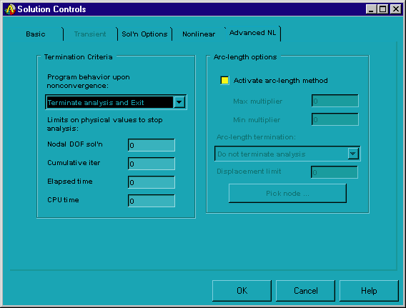
Use the Advanced NL tab to specify the options described below.
- Termination Criteria
[NCNV]--Determines what happens if the analysis fails to converge or specified limits are met. Click the Program behavior upon nonconvergence drop down list box and choose one of these options: Do not terminate analysis, Terminate analysis and Exit, or Terminate but Do Not Exit.
Limits on physical values to stop analysis-- You can also specify limits for one or more of the following physical values:
Nodal DOF sol'n: Terminates if the largest nodal DOF solution value (displacement, temperature, and so on) exceeds this limit.
Cumulative iter: Terminates if the cumulative iteration number exceeds this limit.
Elapsed time: Terminates if the elapsed time (in seconds) exceeds this limit.
CPU time: Terminates if the CPU time (in seconds) exceeds this limit.
- Arc-length Options
[ARCLEN, ARCTRM]--Controls activation and termination of the arc-length method. Click the Activate arc-length method check box to activate it, and then use the Max multiplier and Min multiplier entry boxes to specify the maximum and minimum multipliers of the reference arc-length radius.
Note: You cannot use the arc-length method with the following controls: automatic time stepping, line search, and the DOF solution predictor. If you activate the arc-length method after you set any of these controls, a warning message appears. If you choose to proceed with the arc-length method activation, Mechanical APDL disables your automatic time stepping, line search, and DOF solution predictor settings.
Arc-length termination: Click the drop down list box to specify the basis of solution termination. You can choose one of these options:
Do not terminate analysis: Does not use arc-length option settings as the basis for terminating the analysis.
Terminate at first limit point: Terminates the analysis if the first limit point has been reached. (The first limit point is that point in the response history at which the tangent stiffness matrix becomes singular; in other words, the point at which the structure becomes unstable.)
Terminate at <direction> limit: Terminates the analysis when the displacement in the chosen direction first equals or exceeds a specified limit. The direction can be UX, UY, UZ, ROTX, ROTY, or ROTZ. If you select one of these options, specify the maximum desired displacement (absolute value) in the Displacement limit entry box. (For rotational degrees of freedom, specify the limit in radians rather than in degrees.) Then, click the button and use the picker to pick a node. Mechanical APDL calculates the displacement at the picked node and compares it to the specified limit. When the calculated displacement equals or exceeds the specified limit, the analysis terminates.
For more information about the controls on the Advanced NL tab, see Nonlinear Structural Analysis in the Structural Analysis Guide.
