


To simulate actual conditions, the tire dimensions approximate those of a P215/65R16 car/minivan tire.
An incompressible hyperelastic material model is used for the tire. Reinforcing elements are embedded into the solid elements to model steel reinforcing within the tire structure.
Modeling for this problem involves the following tasks:
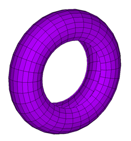
The tire is modeled with SOLID186 solid elements by rotating a 2D meshed area around an axis defined by two key points, as shown:
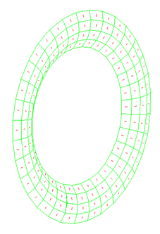
The air inside of the tire is modeled with HSFLD242 hydrostatic fluid elements. The elements are generated (ESURF) with a pressure node ID over the solid elements to enclose the air.
The following figure shows the fluid elements generated over the solid elements:
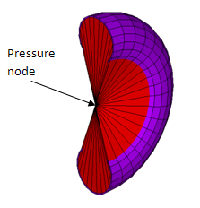
Because the fluid elements are pyramid shaped with common vertices at each pressure node ID, the fluid elements cover some undesired volumes as well. So that fluid elements exist only in the region where air should be present, fluid elements having a negative volume in the undesired region are used, as shown in this figure:
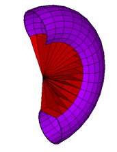
This technique involves manually generating fluid elements with the nodes ordered in a clockwise direction.
The following input example shows how to model the air inside of the tire using hydrostatic fluid element HSFLD242:
! Defining hydrostatic fluid element
Et,3,242           ! Hydrostatic fluid element
keyopt,3,5,1       ! Fluid mass calculated based on the volume
!                      of the fluid element
type,3
mat,2              ! Gas material model used to model the inside fluid
real,3
r,3,0.10156	        ! Initial air pressure (atmospheric) = 0.10156 N/mm^2
n,1,0.,340.,0.     ! Define pressure node

! Selecting solid elements to enclose the fluid
lsel,s,line,,52
lsel,a,line,,53,123,5
lsel,a,line,,130
lsel,a,line,,131,201,5
lsel,a,line,,208
lsel,a,line,,209,279,5
lsel,a,line,,282
lsel,a,line,,283,311,2
nsll,s,1
esln
esurf,1            ! Generate the hydrostatic fluid element over the solid
!                       elements with pressure node.
allsel,all
! Generate the hydrostatic fluid element with negative volume
e,60,284,283,59,   ! Order the node in clockwise direction
emore,1
e,61,285,284,60,
emore,1            ! Similarly more elements are generated in undesired volume
|
For more information about modeling, see Modeling Hydrostatic Fluids and Example Model Using Hydrostatic Fluid Elements in the Structural Analysis Guide. |
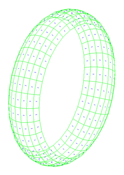
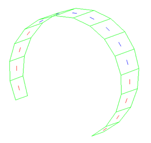
Tire reinforcing is modeled with reinforcing element REINF265. Different material models are used to define the reinforcing in the road contact area and the side walls, as shown in the following figures:
The following input example shows how to model tire reinforcing using REINF265:
! Section definition for reinf1
sectype,13,reinf,smear,reinf13   ! Define section type and
!                                    sub type(smear), 13 is section id number
secdata,4,4,2,,,ELEf,3,0.5       ! Define section data
! For more information, see SECDATA command documentation
!
vsel,s,volu,,5,11                ! Select base element
vsel,a,volu,,20,26
eslv,s
esel,r,type,,2
secn,13                          ! Assign section to reinforcing element
ereinf                           ! Generate reinforcing element
!
! Reinforcing elements are generated similarly in other sections
A rim is modeled as a rigid body using a multipoint constraint (MPC) algorithm (rigid constraints), as shown in this figure:
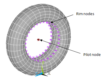
Node-to-surface contact elements (CONTA175) are used for the rim nodes and a target element (TARGE170) is used to define a pilot node at the center of the tire, as shown in the following figure:
The following input example shows how to model the rim:
et,4,175             ! Select contact element
et,5,170             ! Select target element
keyopt,4,2,2         ! Use MPC constraints
keyopt,4,4,0         ! Use rigid surface constraint
keyopt,4,12,5        ! Always bonded
n,1026,0.,340.,0.    ! Make node at axle (pilot node)

! Define target element at pilot node
tshap,pilot
type,5
real,4
e,1026
! Contact element definition
type,4
real,4
! Select contact surface (rim nodes)
lsel,s,line,,51
lsel,a,line,,124
lsel,a,line,,129
lsel,a,line,,202
lsel,a,line,,207
lsel,a,line,,280
lsel,a,line,,281
lsel,a,line,,312
nsll,s,1
esurf                ! Generate contact element
allsel,all
A surface-to-surface contact pair is modeled between the road and tire, as shown in this figure:
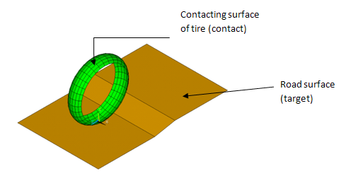
The CONTA174 element is used to model the part of the tire's surface which comes in contact with the road. The road is modeled as a rigid target (TSHAP,QUAD). Impact constraints (KEYOPT(7) = 4) are specified for the contact element.