


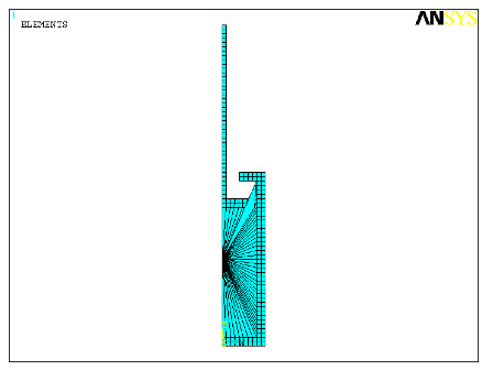
The following example shows an axisymmetric model of a cylinder-piston arrangement. The contained fluid in the cylinder is modeled with hydrostatic fluid elements, shown as triangular elements in the figure below.
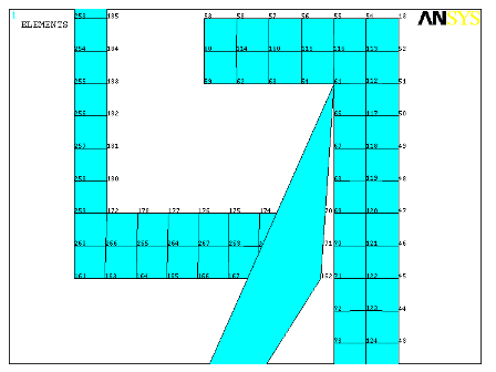
Due to the gap between the cylinder and piston, a hydrostatic fluid element with no underlying solid elements is added manually. The node numbering on this hydrostatic fluid element is reversed to achieve a negative fluid volume that balances the extra fluid volume created by hydrostatic fluid elements attached to the cylinder above the piston. The figure below shows a close-up view of the node numbering in the area where the hydrostatic fluid element with negative volume and no underlying solid element is defined.
The following sequence of commands generates this model, including the hydrostatic fluid elements, material models, and boundary conditions.
/batch,list
/title, Example input data for defining hydrostatic fluid elements
/prep7

!
! Define element types
!

et,1,182	!plane182
keyopt,1,3,1	!axisymmetric option
et,2,241	!hsfld241
keyopt,2,3,1
!
! Define material type
!

! Material properties for Steel
mp,ex,1,2.0e5	!Young's Modulus in N/mm^2
mp,nuxy,1,0.3	!Poisson's ratio
mp,dens,1,7.7e-9!Density in ton/mm^3

! Material properties for hydraulic fluid
tb,fluid,2,,,,liquid
tbdata,1,2000.0	!Bulk Modulus in N/mm^2
tbdata,2,6.4e-4	!Coefficient of thermal expansion
tbdata,3,8.42e-5!Density in ton/mm^3

!
! Define nodes, keypoints, areas
!

! Nodes
n,1,0.0,50.0	!pressure node

! Keypoints
k, 1, 0.0,  0.0
k, 2,25.0,  0.0
k, 3,25.0,100.0
k, 4,10.0,100.0
k, 5,10.0, 95.0
k, 6,20.0, 95.0
k, 7,20.0,  5.0
k, 8, 0.0,  5.0
k, 9, 0.0, 80.0
k,10,19.0, 80.0
k,11,19.0, 85.0
k,12, 2.5, 85.0
k,13, 2.5,185.0
k,14, 0.0,185.0

! Areas
a,1,2,3,4,5,6,7,8
a,9,10,11,12,13,14

!
! Define mesh
!

! Planar elements
type,1
mat,1
esize,2.5
amesh,all

! Hydrostatic fluid elements--automatic generation
type,2
mat,2
lsel,s,line,,6,9
nsll,s,1
esurf,1
allsel,all

! Hydrostatic fluid elements--E command
e,61,162,,1	!element with negative volume--nodes 61 and 162 swapped

!
! Define degree-of-freedom constraints (boundary conditions)
!

! Symmetry boundary condition on pressure node
d,1,ux,0.0

! Symmetry boundary condition on planar mesh
lsel,s,line,,8,14,6
nsll,s,1
d,all,ux,0.0
allsel,all

! Fixed boundary condition on planar mesh
lsel,s,line,,1
nsll,s,1
d,all,all,0.0
allsel,all

finish