


Building a multistage model has two main considerations:
Preparing a single stage for a multistage analysis involves the following steps:
For cyclic sector meshes, there are two key concerns:
To properly prepare the sector to apply cyclic constraints. This is covered in detail later in this chapter (see Multistage Cyclic Boundary Considerations).
To account for the base-duplicate sector method. When preparing a cyclic sector, and if the harmonic index requires it, it may be necessary to have an exact copy of the base sector, which is called the duplicate sector. See Table 3.1: Cases Requiring a Duplicate Sector.
If present in your model, you must ensure that the duplicate sector includes a copy of the following:
The following requirements apply regarding the node and element numberings of the base and duplicate sectors of a stage:
The offset between node and element numbers of the base and duplicate coincident nodes is constant and positive throughout the whole model.
A duplicate sector can always be present in the model but is not always needed. If the duplicate sector is not needed, it can be created and constrained using fixed constraints (D command). See Table 3.1: Cases Requiring a Duplicate Sector.
If a duplicate sector is required (Table 3.1: Cases Requiring a Duplicate Sector):
In Mechanical APDL, it must be created by the user. It is not created automatically. One way to achieve it is to create a .cdb file (CDWRITE command) of the base sector model, and then, in another session, read in the .cdb file (CDREAD command) twice to create the base and duplicate sectors.
In the Mechanical Application, you do not need to create a duplicate sector. If required, it is automatically created immediately after you define a stage object.
All stages (original stage plus cloned stages) must have the same cyclic cylindrical coordinate system. By default, the coordinate system is set to the Z-axis cylindrical coordinate system (CSYS,1). To specify a different, previously defined cylindrical coordinate system, issue MSOPT,CSYS prior to all other MSOPT specifications.
For each stage, you must create node and element components (CM) and specify the component names using the MSOPT command. If you prefer to follow the default nomenclature, component names do not need to be specified; see MSOPT in the Command Reference for details.
To include more than one harmonic in your
analyses, you must set up a multiharmonic group, which includes a single lead harmonic stage, associated with the
primary harmonic index of interest, and one or more secondary harmonics or stage clones to account for additional
harmonic indices. To properly define the multiharmonic group, specify the name
of the lead harmonic stage (Value7 on
MSOPT,NEW ) for all stage clones, and leave
Value7 blank when defining the lead harmonic
stage.
Determining relevant harmonic indices for modeling multiharmonic phenomena — Multistage displacements are the sum of contributions of many harmonic functions, only some of which significantly affect the response. For an example problem that demonstrates how to select relevant harmonic indices (HIs) to include in a multiharmonic multistage cyclic symmetry analysis for an accurate response, see Static Analysis of a 2-Stage Disk with Pinholes. To automate HI selection, use one of the following tools:
The multistage harmonic choice wizard is a Mechanical Application Add-on (see Multistage Harmonic Choice Wizard in the Mechanical Add-ons Guide and a tutorial on its use Calculating the Harmonic Indices for a Multistage Analysis in the Mechanical Tutorials).
Alternatively, you can download a Python script, see Python Script for Selection of Multistage Harmonic Indices in the Mechanical APDL Beta Features .
Surface effect elements, as well as any other additional elements created to support the application of loads and boundary conditions, must also be a part of the stage component if used to apply loads (see SURF Elements in the Element Reference).
Further components may be required for the cyclic edge nodes, but it is also possible to specify a user-defined array parameter containing the cyclic edge node pairs (see the CECYCMS command). If node pairs are not specified with an array parameter, components for the cyclic edge nodes must be specified (CM command) for the base sector only. See the CECYCMS command for naming conventions and defaults.
If a stage is to be modeled using cyclic symmetry boundary conditions, it is important to properly set up the sector mesh and cyclic edges. Cyclic constraints are applied using a combination of the MSOPT and the CECYCMS commands. Note the following considerations and requirements when preparing the model for cyclic constraints in a multistage cyclic analysis:
Only solid and shell elements with the following degrees of freedom are allowed at cyclic edges:
elements with UX, UY, UZ degrees of freedom, or
elements with UX, UY, UZ, ROTX, ROTY, ROTZ degrees of freedom, or
elements with TEMP degrees of freedom.
The cyclic edges are expected to have matching nodes by default, but the cyclic edge nodes can also be mapped by setting
KMAP= ON on the CECYCMS command.Note: To obtain the best results accuracy, you should enforce matched cyclic edge meshes.
The nodes on a cyclic edge are not automatically rotated in CSYS,1 (as is the case for cyclic symmetry analyses initiated with the CYCLIC command).
Make sure that low/high edge components contain only base sector nodes.
Nodes common to the cyclic edge and an interstage boundary must be part of the low/high edge components.
The following topics are relevant to combining stages in a multistage cyclic symmetry analysis:
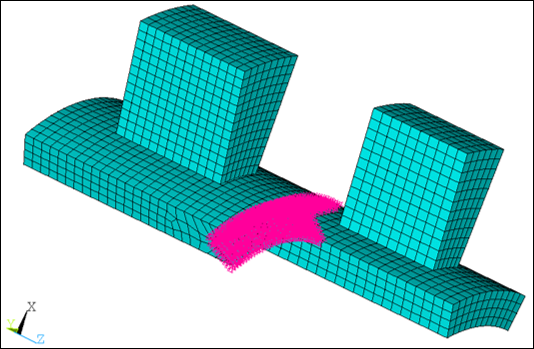
Special constraints are applied at the interstage boundary between multiple cyclic sector stages (Figure 3.1: Two Cyclic Sector Stages Connected at an Interstage Boundary). The coupling of the interstage boundary is performed using the CEIMS command. Verify the following key considerations when defining interstage boundaries:
Only solid elements with UX, UY, UZ or UX, UY, UZ, ROTX, ROTY, ROTZ degrees of freedom are allowed.
For better accuracy, use quadratic elements with preferably the same element type and similar element size on both sides of the interface.
Minimize the gap and penetration between interface boundaries so that they are as nearly flush as possible. Note that the stages meshes do not have to be adjacent to each other in the circumferential direction.
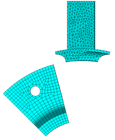
Stages are not required to be oriented in a specific circumferential location relative to each other; they may even be separated. The low cyclic edges of both stages are aligned in Figure 3.1: Two Cyclic Sector Stages Connected at an Interstage Boundary. This is not a requirement. The starting low cyclic sector angle can be arbitrary as shown in Figure 3.2: Inner and Outer Cyclic Stages with Different Sector Starting Circumferential Locations. Keep in mind that sector numbering will start with the sectors as defined prior to solution so the sectors shown in Figure 3.2: Inner and Outer Cyclic Stages with Different Sector Starting Circumferential Locations will be sector 1 for expansion.
The interstage boundaries of adjacent stages do not need to have matching node
or elements. To account for mismatched meshes, mapping is done to relate the
nodes of one stage to the elements of the adjacent stage. To ensure proper
mapping, you must specify the interface nodes in one of two ways using the
CEIMS command: either select the nodes and elements prior
to issuing CEIMS or issue CEIMS and
specify IntF1Nod and
IntF2Nod, the nodal components for both
interstage boundaries (for more details see Applying Interstage Constraints).
A tolerance for the mapping can be specified on the CEIMS command. As long as the mesh is not updated (such as in a nonlinear analysis), it is not necessary to remap for each change of harmonic index.
For details on creating interstage constraints, refer to Applying Interstage Constraints.