The Multistage Harmonic Choice Wizard is a valuable tool for accurately simulating cyclically symmetric systems with multiharmonic phenomena using the multistage analysis procedure. Multistage displacement solutions are the sum of contributions of many harmonic functions, only some of which significantly affect the response. This wizard helps you determine which harmonic indices (HIs) should be included in each stage for an accurate response, a useful tool as:
Including multiple HIs can improve accuracy for models with multiharmonic phenomenon
Including all harmonics in each stage increases the time and computational effort enough to defeat the purpose of multistage modeling
Randomly choosing harmonic indices may lead to a solver error if the chosen HIs are uncoupled, resulting in no constraint equations generated between stages
The Multistage Harmonic Choice Wizard calculates and lists which harmonic indices (HIs) are relevant at each stage by evaluating the relationship between the nodal diameters and HIs. For an example problem demonstrating this and detailing the underlying equations, see Static Analysis of a 2-Stage Disk with Pinholes. For a discussion on the concepts of harmonic index and nodal diameters of a cyclically symmetric structure and their relationship, see Understanding Harmonic Index and Nodal Diameters in the Cyclic Symmetry Analysis Guide.
Note: The wizard is only available for models that include a Stage object with a defined cyclic symmetry region (either a Cyclic Region or Pre-Meshed Cyclic Region object).
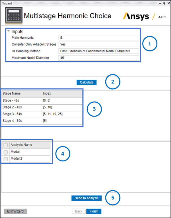
Specify these values in the Wizard dialog in the following order, as shown in the image above:
Inputs Fields for the Wizard
Main Harmonic: Specify the main harmonic index for the response, which depends on the engine order (excitation) of interest. It must be an integer greater than or equal to zero. The maximum available value is the lowest maximum harmonic index of all stages.
Consider Only Adjacent Stages: Select Yes to use the interstage connections that are defined in your model (via Interstage objects) in the calculation of relevant harmonic indices. If it is set to No, the algorithm considers all possible combinations of two stages, regardless of the interstage connections defined in the model.
HI Coupling Method: Select the method used to compute the coupled harmonic indices among the following 3 options (from the minimum to maximum number of coupled harmonic indices):
Fundamental Nodal Diameters: The wizard only calculates the aliased harmonic indices coupled with the main harmonic.
First Extension of Fundamental Nodal Diameters: The wizard extends the previous concept to include higher nodal diameters up to the Maximum Nodal Diameter specified for the main harmonic only.
All Nodal Diameters: The wizard computes all coupled harmonic indices below the Maximum Nodal Diameter specified without restrictions on the main harmonic.
Maximum Nodal Diameter: This field is active if HI Coupling Method is set to First Extension of Fundamental Nodal Diameters or All Nodal Diameters. Enter an integer to specify the nodal diameter range or the maximum number of nodal diameters for which you require an accurate response. This option is not available if the HI Coupling Method is set to Fundamental Nodal Diameters.
Note: Consider the trade-off between accuracy and computational costs when specifying the nodal diameter range:
A low number selects a minimal number of harmonic indices, which is computationally efficient but gives accurate results for a smaller frequency range.
A high number selects more harmonic indices and provides more accurate results over a wider frequency range at the price of higher computational costs.
Calculate Button: Click Calculate after you have specified all inputs, and the wizard generates two tables, listing the calculated indices (see step 3) and all analyses that are included in your model (see step 4).
Calculated Indices Table: This table lists the main harmonic indices required for each stage to establish a baseline of accuracy. These HIs are sent to the analyses selected in steps 4 and 5 for inclusion in your model.
List of Analysis: This table lists all available analyses included in your model. By default, the wizard sends the calculated HIs to all analyses if you do not select one or more specific analyses from the list. Alternatively, select checkboxes to send the calculated HIs only to those specified analyses.
For a list of supported analysis types, see Solving a Multistage Analysis in the Multistage Cyclic Symmetry Analysis Guide.
Send to Analysis: Click this button to send the calculated indices to the respective stages in the analyses selected in step 4.
Note: This action resets the solution state of the Stage object to Solve Required, even if you have previously solved the simulation.
Below are two examples illustrating the application of the wizard using harmonic indices:
Example 3.1: Model with Two Stages (6 and 12 Sectors)
The aim is to find the coupled harmonic indices that match the main harmonic index, HI=1.
| Stage 1 | Stage 2 | |
| Sectors (N) | 6 | 12 |


The first two tables list the nodal diameters for each HI of Stage 1 (Figure 3.4: Nodal Diameter Calculations for Stage 1) and Stage 2 (Figure 3.5: Nodal Diameter Calculations for Stage 2). For Main Harmonic 1, the coupling nodal diameters are 1 and 5 in Stage 1. In Stage 2, the coupling diameters (1 and 5) are found to be part of HI 1 and 5.
Table 3 (Figure 3.6: Harmonic Index Calculations) indicates the coupling Fundamental Nodal Diameters (also referred to as the Main Diagonal) for the Harmonic Indices matrix. The Fundamental Nodal Diameters are represented by the blue band. The coupling indices are represented in green. The Fundamental Nodal Diameters represent aliased/main coupling. Since the HI of Stage 2 is an integral multiple of Stage 1, there are no additional couplings. Therefore, setting HI Coupling Method to First Extension of Fundamental Nodal Diameters or All Nodal Diameters to request additional indices does not cause a change in generated Main Harmonic indices.
Example 3.2: Model with Two Stages (6 and 21 Sectors)
The aim is to find the coupled harmonic indices that match the main harmonic index, H=1.
| Stage 1 | Stage 2 | |
| Sectors | 6 | 21 |

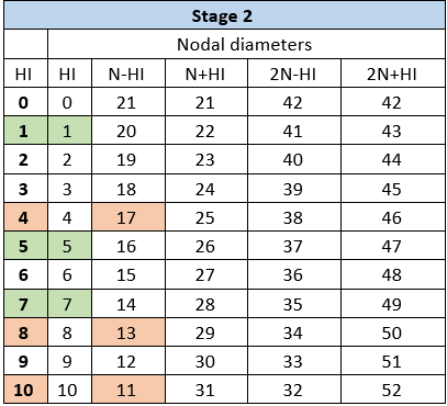

The nodal diameters for each harmonic index of Stage 1 and Stage 2 are listed in Figure 3.7: Nodal Diameter Calculations for Stage 1 and Figure 3.8: Nodal Diameter Calculations for Stage 2.
If HI Coupling Method is set to Fundamental Nodal Diameters, only the nodal diameters below the maximum harmonic index of the stage with the highest number of sectors (in this case, 10) are considered. This corresponds to the nodal diameters in green. This method indicates coupling between the harmonic index 1 of Stage 1 and harmonic indices 1, 5, and 7 of Stage 2. It is also displayed graphically in the aliased main diagonal indicated by the blue arrows in Figure 3.9: Harmonic Index Calculations.
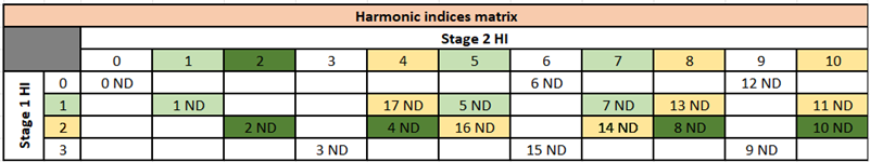
If HI Coupling Method is set to First Extension of Fundamental Nodal Diameters, the wizard selects more harmonics by extending the main diagonal to higher nodal diameters, as illustrated by the orange arrows in Figure 3.9: Harmonic Index Calculations. The process stops at the specified Maximum Nodal Diameter. For a value of 17 nodal diameters, the extra harmonics 4, 8, and 10 of Stage 2 (in orange) which also participate in the response are selected. They correspond respectively to the coupling of the 17th, 13th, and 11th nodal diameters.
If HI Coupling Method is set to All Nodal Diameters, the wizard selects all harmonic indices coupled below the specified Maximum Nodal Diameter inside and outside of the main diagonal by incrementally adding HIs starting from the specified Main Harmonic. In that case, the selected harmonic indices are 1 and 2 for Stage 1 and 1, 2, 4, 5, 7, 8, and 10 for Stage 2, as illustrated in Figure 3.10: Harmonic Index Calculations for All Nodal Diameters. Starting from the Fundamental Nodal Diameters (in light green), it searches for other coupled nodal diameters in those rows and columns below the Maximum Nodal Diameter (yellow cells) and continues the process to find all couplings by finding the dark green nodal diameters next. The remaining white cells with a number of nodal diameters under 17 also represent existing nodal diameter couplings, but with less influence on the input Main Harmonic and are not output by the wizard.