To create the deformable contact surface, you must define that surface using one of the following contact elements:
The contact surface is defined by the set of contact elements that make up the surface of the deformable body. These contact elements have the same geometric characteristics as the underlying elements of the deformable body. The contact surface elements are of the same order as the underlying elements (lower- or higher-order), with compatible nodes along the edges. The higher-order contact elements can match lower-order underlying elements by dropping the midside nodes. The underlying elements can be solid, shell, beam, or pipe elements. The contact surface can be on either side of the shell or beam elements. The underlying elements may also be a superelement. However, axisymmetric harmonic elements may not be used as underlying elements.
As with the target surface elements, you must define the contact surface element type, then select the correct real constant number (the real constant number must be the same as the one used for the target surface for each contact pair), and finally generate the elements.
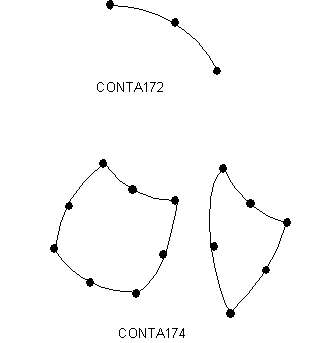
The surface-to-surface contact element types are shown in the figure below, followed by a brief description of each element. For complete information on these element types, see the Element Reference.
CONTA172: This is a 2D, 3-node, higher order parabolic element that can be located on the surfaces of 2D solid or beam elements with or without midside nodes (for example, SHELL208, PLANE183).
CONTA174: This is a 3D, 8-node, higher order quadrilateral element that can be located on the surfaces of 3D solid or shell elements with or without midside nodes (for example, SHELL181, SHELL281). It can be degenerated to 3- to 7-node quadrilateral/triangular shapes.
The following elements can also be defined using the method described here.
CONTA175: This is a 2- or 3D, 1-node element that can be located on the surface of 2D lower order and higher order solid or beam elements or 3D lower order solid or shell elements. Use CONTA175 for node-to-surface contact.
CONTA177: This is a 3D line element that can be located on the surface of 3D beam and pipe elements, on the edge of 3D shell elements, or on the feature edge of 3D solid elements. The element can be a 2-node line or a 3-node parabola, depending on whether the underlying element is lower or higher order. Use CONTA177 to model 3D line-to-surface contact or 3D beam-to-beam (or edge-to-edge) contact.
Use the ET command to define the contact element type.
After defining the element type, you need to select the correct real constant set (REAL command). The real constant set for each contact surface must be the same one used for the corresponding target surface for each contact pair. Each contact pair must reference its own real constant number.
The program uses the material properties of the underlying elements to calculate an appropriate contact (or penalty) stiffness. The program automatically defines a default value for tangent (sliding) contact stiffness that is proportional to MU and the normal stiffness. If the underlying element is a superelement, the material property set for the contact elements must be the same as that of the original structural elements used during the formation of the superelement.
Use the MP command to define the following contact element material properties:
MU - coefficient of friction
EMIS - emissivity (for thermal contact with radiation)
DMPR - damping ratio
DMPS - constant structural damping coefficient
See Damping in the Structural Analysis Guide for more information on DMPR and DMPS.
Note: DMPR and DMPS are only applicable when a penalty-based method is used (KEYOPT(2) = 0 or 1).
You can generate contact elements either through direct generation or by generating the surface automatically from the exterior faces of the underlying elements. Ansys, Inc. recommends that you use automatic generation. This approach is simpler and more reliable.
To automatically generate contact elements, follow these steps:
Select the nodes on the meshed deformable body with the NSEL command. For each surface, view the node list. If you are certain that particular nodes will never come into contact, you can omit those nodes and reduce CPU time. However, you should always include more nodes than you think you'll need so that you don't miss unexpected areas of contact.
Generate the contact elements with the ESURF command.
If the contact surface is attached to areas or volumes that are meshed with solid elements, the program automatically determines the outward normal needed for contact calculations. If the underlying elements are beam or shell elements, you must use the ESURF,,TOP or BOTTOM command to indicate which surface (top or bottom) is the target surface.
Use the TOP setting (default) to generate contact elements with their outward normals the same as the beam or shell elements' normals. Use the BOTTOM setting to generate contact elements with their outward normals opposite the beam or shell elements' normals. You must make sure that all elements in the beam or shell element selection have their normals consistently oriented. If the underlying elements are solid elements, then the TOP or BOTTOM setting has no effect.
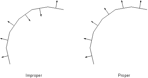
Check the direction of the outward normals for the contact elements with the /PSYMB,ESYS command. The direction of the contact surface's outward normal is critical for proper contact detection. For the 3D surface-to-surface contact element, CONTA174, the node numbering follows the right hand rule to define its outward normal. The contact surface's outward normal should point toward the target surface. Otherwise, the program may detect over-penetration of the surfaces at the beginning of the analysis and have difficulty finding an initial solution. In most of these cases, the analysis will fail immediately. For 3D line-to-surface contact element, CONTA177, the contact nodes must be ordered in a sequence that defines a continuous line. Figure 3.8: Specification of the Contact Surface's Outward Normal illustrates both proper and improper specification of the contact surface's outward normal.
If the surface normals are specified incorrectly, you must either change them by reversing the node number order of the selected elements with the ESURF,,REVE command or reorient the element normals with the ENORM command.


