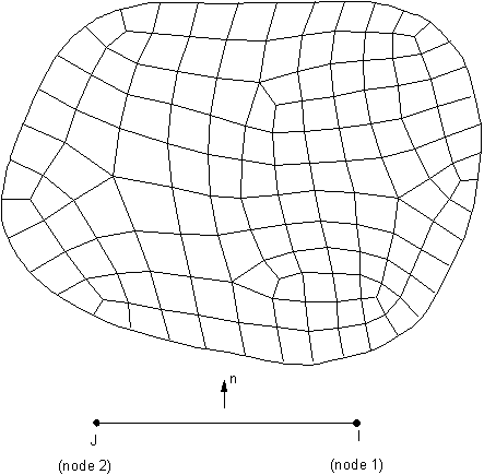
The target surface can be 2D or 3D and either rigid or deformable. For deformable target surfaces, you will normally use the ESURF command to generate the target elements along the boundaries of an existing mesh. You can follow the same method to generate the deformable contact surface (see Defining the Deformable Contact Surface for details). If you are modeling 3D line-to-line contact and the underlying elements are a part of shell edges, issue ESURF,,,LINE to generate 3D line or parabola segments along the shell edges.
You should not use the following rigid target segments for a deformable target surface: ARC, CARC, CIRC, CYL1, CONE, SPHE, POINT, or PILO. For rigid target surfaces, the following provides general guidelines.
In 2D cases, the shape of the target surface is described by a sequence of straight lines, circular arcs, and parabolas, all of which can be represented with the target segment element TARGE169. You can use any combination to define the complex target surface geometry. In 3D cases, the shape of the target surfaces is described by a sequence of triangles, quadrilaterals, straight lines, parabolas, cylinders, cones, and spheres, which can be represented with TARGE170. You can use any reasonable combination of low/high-order triangles and quadrilaterals to model a target surface with a complex, arbitrary geometry.
The rigid target surface can also be associated with a "pilot node," which is really an element with one node, whose motion governs the motion of the entire target surface. You can think of a pilot node as a handle for the rigid target surface. Forces/moments or rotations/displacements for the entire target surface usually should be prescribed on the pilot node. The pilot node can be one of the nodes on the target element or a node at any arbitrary location. The location of the pilot node is important only when rotation or moment loading is required.
You can use circle, cylinder, cone, and sphere primitives to model the target (which require real constants to define the radius). You can combine primitive segments with general segments (such as lines, parabolas, triangles, and quadrilaterals) to define a target surface. Primitives cannot be defined directly in the Contact Wizard. The primitives do not support MPC based bonded or no-separation contact.
Before generating the target element, first use the ET command to define the element type (TARGE169 for 2D or TARGE170 for 3D).
You define characteristics of the target element geometry through real constants R1 and R2 as follows:
For CONTA172:
R1 is the radius if the target shape (TARGE169) is a circle.
R2 is the element thickness if the underlying element is a superelement set as plane stress with thickness (KEYOPT(3) = 3). The default value is 1.
For CONTA174 (also applies to node-to-surface element CONTA175, and to line-to-surface element CONTA177):
R1 is the radius if the target shape (TARGE170) is a cylinder, cone, or sphere.
R2 is the radius of a cone at the second node.
When CONTA177 is used to model 3D beam-to-beam contact:
R1 is the radius of circular beams on the target side (target radius). Use a positive value in all cases (external beam-to-beam contact and internal beam-to-beam contact). To model internal beam-to-beam contact, set KEYOPT(9) = 1 for the associated TARGE170 element type and input R1 as the inner radius of the outer beam.
R2 is the radius of circular beams on the contact side (contact radius). Use a positive value for both external and internal beam-to-beam contact.
To set the real constant number for the target elements, use the REAL command.
For TARGE169 and TARGE170, you need only set real constants R1 and R2 (if required). For a complete description of the target elements, element shapes, and real constants, see the description of TARGE169 and TARGE170.
Note: Specifying real constants (R1, R2) manually is necessary only if you use direct generation to create your target elements, or if you model 3D beam-to-beam contact with CONTA177. You can also use the meshing tools to create the elements, or use the Contact Manager Toolbar.
To generate target elements directly, use the TSHAP command.
You then specify the element shape. Possible shapes are:
Straight line (2D and 3D)
Parabola (2D and 3D)
Clockwise arc (2D)
Counterclockwise arc (2D)
Circle (2D)
Three-node triangle (3D)
Six-node triangle (3D)
Four-node quadrilateral (3D)
Eight-node quadrilateral (3D)
Cylinder (3D)
Cone (3D)
Sphere (3D)
Point (2D or 3D)
Pilot node (2D and 3D)
Once you specify a target element shape, all subsequent elements will have that shape until you specify another shape.
Note: You cannot mix 2D and 3D target elements on the same target surface.
You cannot mix rigid target elements with deformable target elements on the same target surface. During solution, the program assigns a deformable status to target elements with underlying elements and assigns a rigid status to target elements without underlying elements. If a portion of the underlying elements of a deformable surface are deleted, an error will occur in solution.
You can generate the nodes and elements using standard direct-generation techniques (N, E). For more information on direct generation modeling techniques, see Direct Generation in the Modeling and Meshing Guide.
You can then verify your element shapes by listing the elements.
You can allow the program to generate the elements automatically using standard meshing capabilities. The program recognizes the proper target element shape based on the solid model and ignores the TSHAP setting.
To generate a pilot node, use the KMESH command.
To generate POINT segments, use the Direct Generation method or use ESURF,,,POINT command on selected nodes.
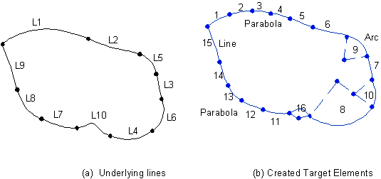
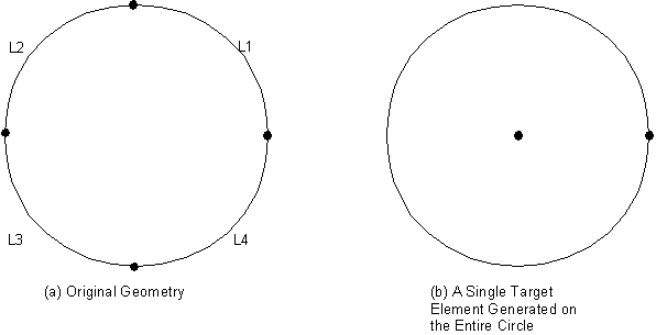
To generate 2D rigid target elements or 3D rigid line/parabola segments, use the LMESH command. The program creates a single line over each line, parabolic segments over B-splines, and arc segments over each arc and line fillet (see Figure 3.2: Geometric Entities and Their Corresponding Rigid Target Elements). If all the arcs form a closed circle, the program creates a single circular segment (see Figure 3.3: A Single Circular Target Segment Created From Arc Line Segments). However, if the arcs that form a closed circle are created from imported or archived geometry (such as IGES), the program might not create a single circular segment.
To generate 3D rigid target elements, use the AMESH command.
If the surface segments on the solid model form a complete sphere, cylinder, or cone, then the program automatically generates a single primitive 3D target element through the AMESH command. By creating fewer elements, the analysis becomes more computationally efficient. For arbitrary surfaces, you should use AMESH to generate target elements. In these cases, the quality of the meshed target shape is not important. It is more important that the target elements represent the rigid surface geometry well.
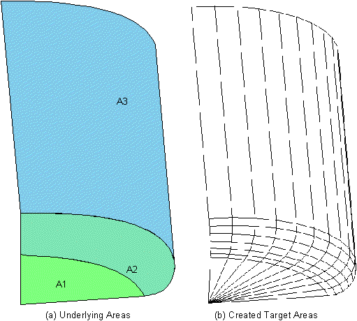
Ansys recommends using mapped meshing on all possible areas. If there is no curvature on the edges of the surface, assign one division on that edge. TARGE169 with a rigid specification will always mesh with one element division, per line, ignoring any LESIZE setting. The default target element shape is quadrilateral. If you want a triangular target element shape, use MSHAPE,1. Figure 3.4: Meshing Patterns for Arbitrary Target Surfaces shows the meshing patterns for arbitrary target surfaces. The MSHKEY,2 command generates a mapped mesh wherever possible (otherwise, if not possible, it will generate a free mesh).
If the target surface is flat (or nearly flat), you may select low-order target elements (3-node triangular or 4-node quadrilateral elements). If the target surface is curved you should select high-order target elements (6-node triangular or 8-node quadrilateral). By doing so, set KEYOPT(1) = 1 in the target element definition.
Note: Low-order target elements result in "cheaper" CPU usage in getting penetration and gap. However, the meshed surface may not be smooth. Higher-order target elements are more "expensive" to use in getting the penetration and gap, but they need many fewer elements to discretize the whole curved target surface.
Note: If target elements are created via program meshing (through the KMESH, LMESH, or ESURF commands) the TSHAP command is ignored and the program chooses the correct shape codes automatically.
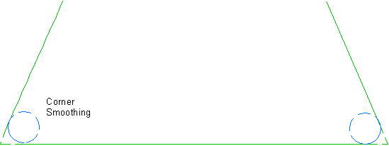
A target surface can be made up of two or more disconnected regions. Where possible, you should localize the contact zone by defining multiple target surfaces (each with a different real constant number). There are no restrictions on the shape of the rigid surfaces. Smoothing is not required. However, you must ensure that the mesh discretization of the curved surfaces on the rigid target surface is adequate. Excessively coarse discretization can cause numerical convergence problems. It can be difficult to obtain a converged solution in a large sliding simulation if the target surface has sharp convex corners. To avoid such modeling problems, use line or area fillet functions on the solid model to smooth out the sharp corner, use a more refined mesh, or use high-order element in the region of abrupt curvature changes (see Figure 3.5: Smoothing Convex Corner).
The node order of the target surface elements is critical because it defines contact direction. For 2D contact, the associated (deformable) contact elements must lie to the right of the target surface when moving from the first node to the second node along the target surface line (see Figure 3.6: Correct Node Ordering).
For 3D contact, the target element numbering should be such that the rigid surface's outward normal points toward the contact surface. The outward normal is determined by the right-hand rule.
For 3D line segments, the target nodes must be numbered in a sequence that defines a continuous line. The line can be made up of linear or parabolic segments, depending on whether the underlying beam is made up of first order or second order elements.
To check the direction of the normals, use the /PSYMB,ESYS,1 commandto turn on the element coordinate systems.
If the element normals do not point toward the contact surface, select this element and reverse the direction of the surface normals with the ESURF,,REVE command.
Alternatively, reorient the element normals with the ENORM command.
Note: Contact on target primitives (such as a complete circle, cylinder, cone, or sphere), can occur only on the outside surfaces of such target bodies.
Modeling contact on either side of a shell surface or a standalone rigid surface generally requires you to have two sets of the target surface with opposite surface normals.
By setting the double-sided target surface option (KEYOPT(8) = 1 of the TARGE170 target element type), you can model double-sided contact pairs with only one set of the target surface. This option not only reduces the total number of target elements, but also solves big assembly models where the orientations of underlying shell elements are not obvious or not consistent. It also helps to solve models in which target elements are imported from third-party packages that generate meshes, or generated directly using E, EN, or EBLOCK commands.
This double-sided target surface operation requires a consistent element normal in the contact surface for each connecting region, but allows an arbitrary element normal in the target surface. Contact is detected based on the smallest distance of either gap or penetration for each contact constraint. The double-sided target surface option is only valid for 3D models with:
Surface-to-surface contacts (CONTA174) with Gauss detection (KEYOPT(4) = 0), with "Normal from contact nodes" (KEYOPT(4) = 1), and with “Normal to the target surface" (KEYOPT(4) = 2).
Node-to-surface contacts (CONTA175) with "Normal from contact nodes" (KEYOPT(4) = 1,2), and with “Normal to the target surface" (KEYOPT(4) = 0,3).
For a double-sided target surface, it is not necessary for the normals of all underlying shell elements to have a consistent orientation. However, the program still prefers to have consistent surface normals as much as possible for the generated target elements within each connecting region. A warning message will be issued for either single- or double-sided target surface if any face normals of two adjacent target segments point in opposite directions. In this case, issue the ENORM command to reorient the element normal to be consistent.
Because of the lack of a unique outward direction from a double-sided target surface, the following features are not recommended when using the double-sided target surface options:
Symmetric and auto-asymmetric (KEYOPT(8) = 2 of the contact element) contact pairs definitions
Initial interface adjustment: CNCHECK,
Option= ADJUST, MORPH, or TADJUSTFluid penetration loads applied on target elements


