


SFCONTROL
SFCONTROL, KCSYS,
LCOMP, VAL1,
VAL2, VAL3,
KTAPER, KUSE,
KAREA, KPROJ,
KFOLLOW
Defines structural surface-load properties on selected elements and nodes for
subsequent loading commands.
-
KCSYS Specifies how the load direction is determined:
0 (or blank) – Use the coordinate system of an element face. A local coordinate system is projected onto the face, if defined ( VAL1) (default).1 – Use a local coordinate system. A local coordinate system must be defined and is not projected onto the face. 2 – Use a custom (user-defined) vector in the global Cartesian coordinate system. -
LCOMP Load-component definition when
KCSYS= 0 or 1. The following table shows how the component (or primary direction) is determined based on the coordinate system:LCOMP [a] Direction KCSYS = 0 KCSYS = 1[b] VAL1 = 0 VAL1 > 10[c] -- 0
1
2
Normal
x direction[d]
y direction[d]
Normal
x direction[e]
y direction[e]
x direction
y direction
z direction
[a] Because
KCSYS= 0 andKCSYS= 1 use the sameLCOMP, the most recent load-component definition overwrites the previous component even ifKCSYSdiffers.[b] The local coordinate system is not projected onto the element face.
[c]
VAL1< 0 is not valid. 0 <VAL1< 11 is ignored.[d] The positive x and y directions are determined by the default surface coordinate directions. (See Figure 20: Coordinate System for Load Application on the Faces of 3D Solid and Shell Elements.)
[e] The positive x and y directions are determined by the user-defined local coordinate system.
-
VAL1, VAL2, VAL3 When
KCSYS= 0:VAL1– Determines the first tangential axis (x axis). Not valid for the edges of 3D shell or 2D elements.0 – Aligns the x axis to the first parametric direction  (default).
1 – Aligns x axis to the second parametric direction  .
. >10 – ID of the local coordinate system. The local coordinate system is projected to selected face of the element. VAL2– Not used.VAL3– Rotation angle of a tangential load (optional). Not valid for the edges of 3D shell or 2D elements. If this value is specified, the tangential load rotates further with respect to the surface normal. The load component (LCOMP) becomes the reference axis to rotate.When
KCSYS= 1:VAL1– ID of the local coordinate system for the load. The axes of the local coordinate system are fixed in the global cartesian coordinate system.VAL2– Not used.VAL3– Not used.When
KCSYS= 2:VAL1,VAL2,VAL3– The X / Y / Z components, respectively, of the direction vector in the global Cartesian coordinate system.-
KTAPER Global tapered load behavior (valid for SFE only):
0 – Load does not vary (default). 1 – Load varies with respect to the current element locations. The magnitude changes with respect to the element deformation. 2 – Load varies with respect to the initial element locations. The load magnitude for each element remains constant throughout the solution. . For more information, see "Global Tapered Load Behavior (
KTAPER)".-
KUSE Load direction with respect to the surface normal of the selected face:
0 – Use the load as calculated (default). 1 – Use a positive load only (negative set to zero, valid for LCOMP= 0 andKCSYS= 0).2 – Use a negative load only (positive set to zero, valid for LCOMP= 0 andKCSYS= 0).3 – Applied load is not used if the surface normal is oriented in the same general direction as the user-defined vector. Valid for KCSYS= 2 only.-
KAREA Loaded area during large deformation:
0 – Use the current (deformed) area (default). 1 – Use the initial area. -
KPROJ Vector-oriented load (
KCSYS= 2) behavior:0 – Apply the load on the full area and include the tangential component (default). 1 – Apply the load on the projected area and include the tangential component. 2 – Apply the load on the projected area and exclude the tangential component. -
KFOLLOW Controls follower-load behavior. Valid when
KCSYS= 1 or 2, or whenKCSYS= 0 andVAL1> 10.0 – The load maintains a fixed direction (default). 1 –The load follows the element deformation. For more information, see "Follower Load Behavior".
Notes
SFCONTROL defines the properties of structural distributed loads for all subsequent SF or SFE loading commands. (SFA and SFL are not supported.)
The command does not support 2D-to-3D analysis.
To update a load property or properties, reissue SFCONTROL with the new option(s) before issuing further SF or SFE commands.
|
SFCONTROL supports these structural solid, shell, solid-shell, and coupled-field elements: SHELL181, PLANE182, PLANE183, SOLID185, SOLID186, SOLID187, SOLSH190, SHELL208, SHELL209, SHELL281, SOLID285, PLANE222, PLANE223, SOLID225, SOLID226, and SOLID227. |
To list the current set of control data, issue SFCONTROL,STAT.
To reset all input values to defaults, issue SFCONTROL,NONE.
When KCSYS = 0, the positive normal load
acts in the negative surface normal (-z) direction. The positive
tangential loads act in the positive coordinate direction. A user-defined coordinate system
(VAL1) is ignored if the load is applied on an edge of a plane
element (PLANE182, PLANE183,
SHELL208, SHELL209,
PLANE222, and PLANE223).
When KCSYS = 1, the loading direction
follows the positive direction of the local coordinate system. The ID of a local coordinate
system (VAL1) is required.
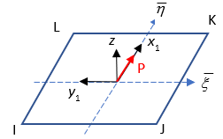
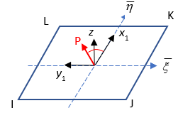
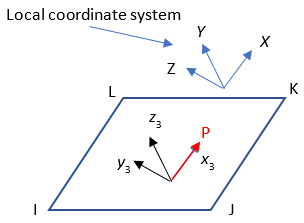
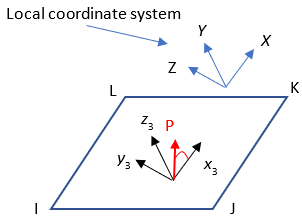
The following figure shows how the coordinate directions are
determined on a face of a solid or shell element with different
KCSYS and VAL1 input:
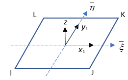
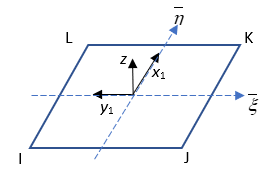
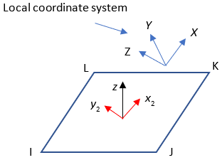
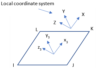
Figure 20: Coordinate System for Load Application on the Faces of 3D Solid and Shell Elements
KCSYS = 0 |
KCSYS = 1 | |
VAL1 = 0 |
| – |
VAL1 = 1 |
| – |
VAL1 > 10 |
|
|
| where: |
| z, x1, y1 : normal and tangential directions (default surface coordinate system) |
| z, x2, y2 : normal and user-defined tangential directions (user-defined surface coordinate system) |
x3, y3, z3 : x,
y, and z directions defined by the local coordinate system when
KCSYS = 1 |
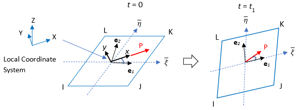
When KCSYS =
0:
The parametric direction determines the default coordinate system on a face. By
default, the first parametric direction () becomes the first tangential direction (x direction). If
VAL1 = 1, the second parametric direction () is selected as the x direction. |
For the projected local coordinate system (VAL1 > 10), the
direction of the first tangential axes (x2) is determined by the
projection of the local coordinate system onto the face. The projected tangential axes may
rotate if the direction of the face normal (z) changes in the space during solution. If the
direction of the face normal (z) is fixed (for in-plane rotation, for example), the
tangential axes do not follow element deformation. To enable your coordinate system to
always follow the element deformation, specify the follower option
(KFOLLOW). |
| Coordinate System vs. Load Direction |
For the loads defined in the default coordinate system
(KCSYS = 0), the tangential direction of a load is restricted
because it is aligned to the direction of the axis (LCOMP). The
load direction can be arbitrary by adding additional rotation to the load
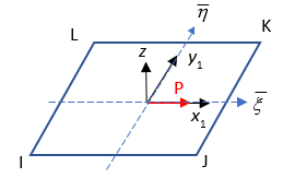
(VAL3). The following figure shows how the load direction is
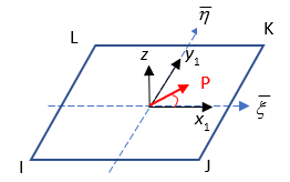
determined on the face of an element. If VAL3 > 0,
LCOMP becomes the reference axis to define the
rotation. |
Figure 21: Load Direction in the Default Coordinate System
VAL3 = 0 |
VAL3 > 0 | |
|
|
|
|
|
|
|
|
|
|
|
|
When KCSYS = 1:
| The positive direction of the x3, y3, and z3 axes follow the direction of the local coordinate system without adjustment. Therefore, they do not follow element deformation. |
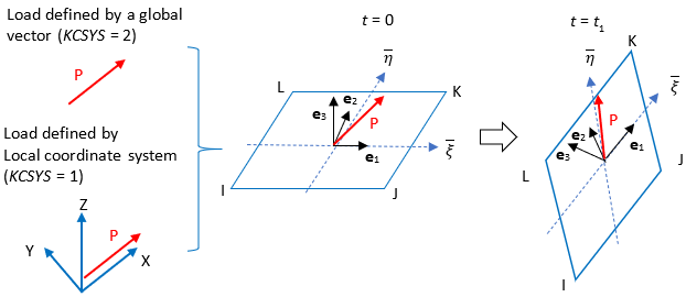
When KCSYS = 2:
The loading direction follows the positive direction of the orientation vector,
defined via VAL1, VAL2, and
VAL3. The direction is calculated as  , where , where  , ,  , and , and  are unit vectors in the global Cartesian coordinate system. The loading
direction is fixed and does not follow the deformation of a face of a selected element. are unit vectors in the global Cartesian coordinate system. The loading
direction is fixed and does not follow the deformation of a face of a selected element. |
You can adjust the load magnitude (KUSE and
KPROJ). |
Use the follower option (KFOLLOW) to
specify whether the load has a fixed direction (KCSYS = 1 or 2),
or projects the local coordinate system to the element face to follow element deformation
(KCSYS = 0 and VAL1 > 10) . |
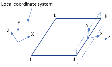
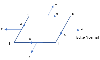
The following figure shows the default direction of the normal (z) and tangential (x) components on an edge of a 3D shell element (SHELL181 or SHELL281).
If a local coordinate system is defined and KCSYS = 0 for the
edge of the 3D shell element, the tangential directions are adjusted in the plane of the
edge.
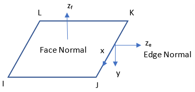
The following figure shows the positive direction of the loads on the edge of a plane
element when KCSYS = 0. The positive direction of the tangential
load is defined by the definition of the faces (J-I, K-J, L-K, I-L).
If KCSYS = 1 or 2, the load direction does not change and
KUSE = 1 or 2 is ignored.
If KCSYS = 1 or 2, or KTAPER > 0,
you cannot specify a gradient (slope) for surface loads (SFGRAD) or a
varying surface load (SFFUN).
This command is also valid in the PREP7 processor.
Global Tapered Load Behavior (KTAPER)
If KTAPER = 1, the magnitude of the load is determined by the
current location of a point:

| where: |
 : Values on SFE ( : Values on SFE (VAL1 ~
VAL4) |
 : Global Cartesian coordinates at the current location of the
point. : Global Cartesian coordinates at the current location of the
point. |
If KTAPER = 2, the magnitude of the load is determined by the
initial location of a point:

| where: |
 : Values on SFE ( : Values on SFE (VAL1 ~
VAL4) |
 : Global Cartesian coordinates at the initial location of the
point. : Global Cartesian coordinates at the initial location of the
point. |
KTAPER is not valid for use with SF.
Follower Load Behavior
The follower option (KFOLLOW) determines whether the load
maintains a fixed direction (default) or follows element deformation. The option applies to
surface loads defined by a fixed direction (KCSYS = 1 or 2) or by
a projected user-defined coordinate system (KCSYS = 0 and
VAL1 > 10).
When KCSYS = 0 and
VAL1 > 10:
The selected local coordinate system is projected onto the face at the initial state,
then the projected tangential component (LCOMP) is attached to
the orthonormal basis (e1, e2, e3) of the face. The orthonormal basis may or may not
be coincident to the  coordinate system. During solution, the basis is updated at the current
time step and the load direction is updated with respect to the basis.
coordinate system. During solution, the basis is updated at the current
time step and the load direction is updated with respect to the basis.
When KCSYS = 1 or 2:
The global direction vector is attached to the orthonormal basis of selected face at the
initial state. When KCSYS = 1, the direction of selected axis is
considered as the direction vector and attached to the basis. During solution, the basis is
updated at current time step and the load direction is updated with respect to the
basis.
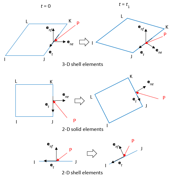
Follower loads on the edges of 3D shell and 2D elements:
The load is attached to the basis defined on the edge (et, ene, enf [tangential, edge-normal, and face-normal vector, respectively]). For 2D solid elements, the face-normal orientation (enf) is that of the global Z axis. For 2D shell elements, the edge-normal (ene) is that of the global Z axis.
If it is necessary to use the follower option after the first load step or at the
restart analysis, define the load direction with respect to the current geometry (that is,
the current basis of an element face). The follower option for the local coordinate system
(KCSYS = 1) is not allowed after the first load step or at the
restart analysis.
Load-Stiffness Effects
Load-stiffness effects are included in the supported elements for the real part of all loads at the current configuration. All other load properties are included in the load vector of the elements.
You can specify an unsymmetric matrix (NROPT,UNSYM) for the load-stiffness effects if needed.