


DED process simulations in Mechanical are performed using the DED Process Add-on, referred to as an ACT extension in previous releases. An Additive Suite license is required to use the add-on.
Loading the DED Process Add-on
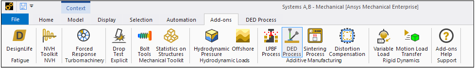
Click the Add-ons tab to show the available Mechanical add-ons. Simply click the DED Process button (in the Additive Manufacturing group) to load the DED Process Add-on. When the add-on is loaded, the button is shaded blue and a DED Process tab is available, as shown in the following figure.
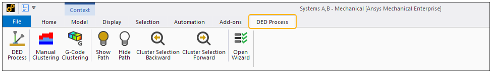
Click the DED Process tab to access the custom ribbon, which includes a step-by-step wizard as well as custom load and result objects. These and other features will be discussed throughout this guide.
Target Users
Target users of additive simulations in Mechanical are the engineers involved in the design and analysis of mechanical components, but also manufacturing engineers and technicians tasked with printing the parts on the machine floor as well as the R&D researchers responsible for optimizing the ideal printing process. Current users of Ansys SpaceClaim and Workbench/Mechanical will benefit greatly from running DED process simulations if they plan to use DED additive manufacturing to print their metal parts.
Simulation Goals
The goal of a DED process simulation is to predict the macro-level, temperature-induced distortions and stresses in parts to prevent build failures, and provide trend data for improving designs for additive manufacturing including part orientation and part build order.
The simulation is not meant to provide detailed thermal or structural results needed for prediction of micro-level process phenomena (that is, microstructure). The simulation will also not provide detailed modeling of the welding melt pool. Our complementary offering of Ansys Fluent is the product to use to achieve that goal.
Methodology and Abstractions
Simulation of the Direct Energy Deposition (DED) manufacturing process requires that the analysis follows the print process itself: weld track-by-weld track solidification of the part. Since the thermal (temperatures) and structural (distortion and stress) physics are largely uncoupled (that is, a weak coupling), we can simulate the thermal phenomena first and use those temperature results in a following structural simulation.
In a DED process simulation, the model evolves over time, that is, elements are added. We actually mesh the entire part first with Cartesian or Tetrahedron elements and then, using the standard element birth and death technique, deactivate all the elements initially and then progressively activate element clusters to simulate the advancing build. Here, a cluster is defined as a portion of the weld track. Furthermore, the relevant boundary conditions such as thermal convection surfaces also evolve. The build process reaches completion when all of the element clusters have been activated (made "alive"). See Understanding Element Birth and Death in the Advanced Analysis Guide.
The analysis times and time stepping are also driven by the process parameters and are not known a priori. These details are all handled internally during the solution.
Although a DED process and an LPBF process are similar in some ways, the DED process needs to have a much more detailed level of simulation. A layer-wise simulation is not accurate enough since the velocity of energy deposition is higher in a DED process and so simulation along the weld track over time is required. As the LPBF process simulation uses abstractions like super layers (lumping multiple layers for simulation) and layer-by-layer addition (instantaneous element activation for an entire layer), the DED process simulation uses the real welding seams and an abstraction known as element clustering. Clustering is used to split weld lines into smaller pieces of mesh, called clusters, that are exposed to one temperature in a time step. Thus, each cluster is a portion of a weld track that is instantaneously activated using the element birth and death technique. Element clusters are deposited following the deformed shape beneath them rather than in the original undeformed location. You control the size of the cluster with a Cluster Volume option. The solve time and solution fidelity are directly related to cluster volume. The building order of the part can be defined by either applying the G-Code machine file or by using a manual approach of carefully-defined named selections.
A DED process simulation uses the following abstractions to meet the goals in a reasonable compute time, meaning much less than the actual build time:
Macro-level welding simulation: The welding melt pool will not be explicitly modeled. The deposited material, whether it is a wire or powder, will be exposed by activating single clusters of elements at a defined temperature equal or close to melting temperature. Phenomena such as phase transition will be captured with the capabilities of engineering data or imported materials rather than simulating these phenomena.
Clustering: Clustering is used to split weld lines into smaller pieces of mesh, or clusters, that are exposed to one heat application in a time step. This approach is required to provide the required accuracy while, on the other hand, limit the simulation time. You define the cluster volume to control the simulation.
Heat Application: Heat is applied to new clusters in one of two ways, either an applied temperature or a power-based heat generation. For applied temperature, the assumption is that the process parameters for the build have been set appropriately so that (1) the developed temperature is always at or above melt (no lack of fusion) and (2) the developed temperature does not substantially exceed melt (no keyholing).
For power-based heat generation, the laser power and absorptivity are specified and a heat
generation load (via BFE,,HGEN) is applied to elements in the new
cluster. The value for HGEN is determined based on how much energy (power, time for
deposition, and so on) goes into each cluster. That energy is then applied over a time span
represented by  in the following equation:

where  is laser power
 is absorptivity
 is deposition rate
 is simulation loading applied time. The time is controlled indirectly
using the Thermal Calibration
setting:
is simulation loading applied time. The time is controlled indirectly
using the Thermal Calibration
setting:
If Thermal Calibration is Off,
 seconds.
If Thermal Calibration is On, the Cluster Cooling Time Ratio is defined as
 and
and  seconds.
  is the volume of current cluster.
Time step size: Large integration time step sizes are used throughout the simulation. This is sufficient to capture the induced thermal and plastic strains driving the distortion. The localized smooth heating and cooling curves will not be captured in detail.
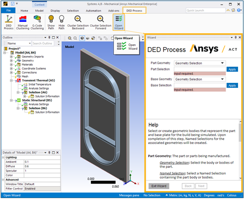
The DED Process Wizard
Included within the DED Process Add-on is an easy-to-use DED Process Wizard. We strongly recommend you use the wizard, as it streamlines and simplifies the simulation process. The wizard is an excellent tool to keep you on track and prevent you from missing a task. There are a few capabilities that are not available in the DED Process Wizard but you can easily modify your simulation set-up when you complete the wizard as it does not include a solve.
Known Issues and Limitations
Review the following issues and limitations for the DED Process Add-on:
General Simulation Setup Limitations:
The DED Process Add-on is not supported on the Linux operating system.
The DED Process Add-on requires units to be millimeters. The add-on checks the unit system and, if necessary, automatically changes it to the Metric system (mm, t, N, s, mV, mA). This check is triggered when you open the DED Process Wizard and/or when you add the AM Process for DED object into the project tree.
If you use a Mechanical Model from Workbench's Component Systems, you must manually create the AM DED Process system. This is due to the fact that AM Custom Systems are pre-populated with AM sample materials in Engineering Data, and linking to the Mechanical Model requires the absence of materials in Engineering Data.
The DED Process Add-on does not account for symmetry so the entire geometry must be included in the simulation model.
In order for DED simulations to solve using Remote Solve Manager (RSM), you must first enable the appropriate files to be downloaded. Add the file types *.comps;*.par;*.rth in Solve Process Settings under Advanced > Additional Files to Download. Enter the file types as shown, with semicolons and no spaces between file types.
When resuming/restoring an archived DED project created with a version of Mechanical prior to Release 2023 R1, you will need to clear generated cluster data, generate clusters again, and then solve the simulation anew, even if you don't modify any inputs. This is because, beginning with Release 2023 R1, additional inputs are required on the clustering object and Cluster Settings is automatically added as a child object.
DED simulations archived from release 2022 R1 (when the DED extension was first introduced) are incompatible with later releases. We recommend that you start over with those models in a later release.
G-Code Clustering Limitations:
When using G-Code clustering, the placement of the G-Code path must align with the printing part's global coordinate system. We assume a planar tool path in the X-Y, X-Z, or Y-Z plane, normal to print direction.
A known issue exists in which results may be invalid when G-Code clustering does not follow the G-Code path. Always check the progression of element clusters after performing clustering to be sure the clusters follow the G-Code path as expected. For more information about this limitation, see Known Issue where G-Code Clustering Does Not Follow the G-Code Path.
The G-Code-Reader does not consider the values of the G-Code E-Command. (See Supported G-Code Commands). Only E0.0 is interpreted as no material deposition. The actual value of the material deposition rate is defined in the Build Settings.
Do not change names of element clusters that are automatically generated using G-Code clustering. Doing so may cause errors during solution.
Manual Clustering Limitations:
We recommend using hex elements rather than tetrahedrons when using manual clustering. For some geometries, some tetrahedrons may be excluded from element clusters.
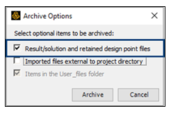
When archiving a DED project and you used manual clustering, check the option to archive result files with the archived project:
If you change the mesh size and remesh after manually generating clusters, the existing cluster named selections are suppressed. However, re-generation of the clusters and named selections does not delete previously suppressed named selections, causing an issue when solving the thermal simulation. The workaround is to delete the suppressed named selections manually before running the solve.
For the very specific workflow related to suppressing a body, the transient thermal portion of the simulation is unable to solve and an error about cluster settings is produced. The workflow is:
Generate clusters for a Manual Clustering object
Suppress a build body
Clear Generated Data on the Manual Clustering object
Generate clusters again on the Manual Clustering object
The workaround is to clear Generated Data from the AM Process for DED object rather than the Manual Clustering object.
Loads, Solution, and Results Limitations:
When working through the project tree (assign materials step), if you leave the Reference Temperature for the print/part geometry set to By Environment, or set to it By Body but leave the Reference Temperature Value at the default of 22°, you may see odd behavior in the structural results, such as missing elements. We recommend that you set Reference Temperature to By Body and set the Reference Temperature Value to the melting temperature of your chosen material. When you use the DED Process Wizard, the Reference Temperature Value is automatically set to the melting temperature of the material, or 1000°C if the melting temperature is not defined for the assigned material.
A bolt pretension boundary condition is not supported in the DED add-on and will result in an error in the structural solution.
We recommend you do not add extra thermal boundary conditions/loads on the model other than radiation and the convection boundary conditions described in this user guide—these are, a) the convection from the part to the surrounding gas in the chamber during printing and cooldown that is set in Build Settings and b) the preheat on the underside of the base. Adding extra loads may cause errors, non-convergence, temperatures to be held at unrealistic values, or other unforeseen behaviors.
Occasionally you may see unexpected, high negative temperatures in the Transient Thermal analysis in the first layer between the part and the base plate. This is a known issue related to severe thermal gradients. These temperature spikes may be reduced somewhat by changing from quadratic to linear elements and/or reducing the element size for the part and/or base plate. These negative temperature spikes may be ignored as they do not have any appreciable effect on the results.
To change from quadratic to linear elements, re-mesh the model with linear elements or use the EMID,REMOVE,ALL command to remove midside nodes from the existing model. A new solution is required.
Starting with Release 2023 R1, default contact options are set such that these high temperature spikes are usually eliminated.
Restarts are not supported in the DED add-on.
High Performance Computing
An AM Process Simulation can be very compute intensive. We recommend you use high performance computing using an Ansys HPC license to take advantage of more than four cores.