


Within a DED process simulation, we use G-Code commands to create clusters of elements that represent the building sequence of the part. Since G-Code can contain extensions and variations specific to machine tool manufacturers and control manufacturers, we focus on basic commands for linear movement (G00 and G01) and circular movement (CIP), and assume a planar tool path in the X-Y, X-Z, or Y-Z plane, normal to print direction. The following table shows supported G-Code commands:
| Command | Function and Parameter | Visualization | UI Options | Examples |
|---|---|---|---|---|
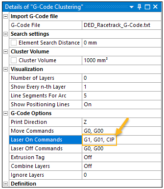
| Arbitrary command | Switch Laser On | N/A | Laser On Commands to specify one or more commands, comma separated | G01 M24 |
| Arbitrary command | Switch Laser Off | N/A | Laser Off Commands to specify one or more commands, comma separated | G00 M28 |
| Arbitrary command | Movement X0.0 Y0.0 Z0.0 | If previous command is Laser Off: Blue line from last position If previous command is Laser On: Green line from last position | Move Commands to specify one or more commands, comma
separated Extrusion Tag option to On if E-Parameter is defined Show Positioning Lines option to Off to suppress visualization | G00 X1.0 Y0.0 Z0.0 G01 X1.0 Y0.0 G01 X1.0 Y0.0 E1.0 |
| CIP | Circle defined by intermediate position (I, J, K) and end position (X, Y, Z) | Green line segments | Show Positioning Lines option to Off to suppress visualization | CIP I1=1.0 J1=1.0 K1=0.0 X2.0 Y0.0 Z0.0 |
| X | Linear movement X0.0 | If previous command is Laser Off: Blue line from last position If previous command is Laser On: Green line from last position | Show Positioning Lines option to Off to suppress visualization | X1.0 Y0.0 |
| Y | Linear movement Y0.0 | If previous command is Laser Off: Blue line from last position If previous command is Laser On: Green line from last position | Show Positioning Lines option to Off to suppress visualization | Y1.0 |
| Z | Linear movement Z0.0 | If previous command is Laser Off: Blue line from last position If previous command is Laser On: Green line from last position | Show Positioning Lines option to Off to suppress visualization | Z1.0 |
| G90 | Switch to absolute positioning for the following commands | N/A | Default | G90 G01 X1.0 G01 X2.0 G90 G01 X1.0 Z1.0 |
| G91 | Switch to relative positioning for the following commands | N/A | Default | G91 G01 X1.0 G01 X2.0 G91 G01 X1.0 Z1.0 |
| F | Feed Rate | N/A | F200 | |
| T | Preheat Temperature | N/A | ||
| G4 | Dwell Time The following variations, as used in various machines, are supported:
| N/A | G4 P700 |
A G-Code file must be in ASCII format. Following is an example of a G-Code text file from the racetrack example used throughout this document.
G00 X-100.0 Y-83.5 Z0.0
; First layer
G00 X-54.0 Y-83.5 Z3.0
G01 X-49.9 Y-104.2 ; Circle 1
G01 X-38.2 Y-121.7
G01 X-20.7 Y-133.4
G01 X0.0 Y-137.5
G01 X20.7 Y-133.4
G01 X38.2 Y-121.7
G01 X49.9 Y-104.2
G01 X54.0 Y-83.5
G01 X54.0 Y80.2 ; Y-Line 1
G01 X49.9 Y100.9 ; Circle 2
G01 X38.2 Y118.4
G01 X20.7 Y130.1
G01 X0.0 Y134.2
G01 X-20.7 Y130.1
G01 X-38.2 Y118.4
G01 X-49.9 Y100.9
G01 X-54.0 Y80.2
G01 X-54.0 Y-83.5 ; Y-Line 2
G00 X-54.0 Y-64.6
G01 X54.0 Y-64.6 ; X-Line 1
G00 X-54.0 Y63.4
G01 X54.0 Y63.4 ; X-Line 2
; Next layer
G00 X-54.0 Y-83.5 Z6.0
G01 X-49.9 Y-104.2 ; Circle 1
G01 X-38.2 Y-121.7
G01 X-20.7 Y-133.4
G01 X0.0 Y-137.5
G01 X20.7 Y-133.4
G01 X38.2 Y-121.7
G01 X49.9 Y-104.2
G01 X54.0 Y-83.5
G01 X54.0 Y80.2 ; Y-Line 1
G01 X49.9 Y100.9 ; Circle 2
G01 X38.2 Y118.4
G01 X20.7 Y130.1
G01 X0.0 Y134.2
G01 X-20.7 Y130.1
G01 X-38.2 Y118.4
G01 X-49.9 Y100.9
G01 X-54.0 Y80.2
G01 X-54.0 Y-83.5 ; Y-Line 2
G00 X-54.0 Y-64.6
G01 X54.0 Y-64.6 ; X-Line 1
G00 X-54.0 Y63.4
G01 X54.0 Y63.4 ; X-Line 2
; Next layer
G00 X-54.0 Y-83.5 Z9.0
G01 X-49.9 Y-104.2 ; Circle 1
G01 X-38.2 Y-121.7
G01 X-20.7 Y-133.4
G01 X0.0 Y-137.5
G01 X20.7 Y-133.4
G01 X38.2 Y-121.7
G01 X49.9 Y-104.2
G01 X54.0 Y-83.5
G01 X54.0 Y80.2 ; Y-Line 1
G01 X49.9 Y100.9 ; Circle 2
G01 X38.2 Y118.4
G01 X20.7 Y130.1
G01 X0.0 Y134.2
G01 X-20.7 Y130.1
G01 X-38.2 Y118.4
G01 X-49.9 Y100.9
G01 X-54.0 Y80.2
G01 X-54.0 Y-83.5 ; Y-Line 2
G00 X-54.0 Y-64.6
G01 X54.0 Y-64.6 ; X-Line 1
G00 X-54.0 Y63.4
G01 X54.0 Y63.4 ; X-Line 2
; Next layer
G00 X-54.0 Y-83.5 Z12.0
G01 X-49.9 Y-104.2 ; Circle 1
G01 X-38.2 Y-121.7
G01 X-20.7 Y-133.4
G01 X0.0 Y-137.5
G01 X20.7 Y-133.4
G01 X38.2 Y-121.7
G01 X49.9 Y-104.2
G01 X54.0 Y-83.5
G01 X54.0 Y80.2 ; Y-Line 1
G01 X49.9 Y100.9 ; Circle 2
G01 X38.2 Y118.4
G01 X20.7 Y130.1
G01 X0.0 Y134.2
G01 X-20.7 Y130.1
G01 X-38.2 Y118.4
G01 X-49.9 Y100.9
G01 X-54.0 Y80.2
G01 X-54.0 Y-83.5 ; Y-Line 2
G00 X-54.0 Y-64.6
G01 X54.0 Y-64.6 ; X-Line 1
G00 X-54.0 Y63.4
G01 X54.0 Y63.4 ; X-Line 2
Circular Movement (CIP)
When using the CIP command for circular movement, two things are required:
CIP must be added to the Laser On Commands option in the G-Code Clustering object.
The circular movement must be defined correctly in the G-Code itself. Any arc can be defined by three points. Within the G-Code file, the following points define an arc:
Starting point—obtained from the last G-Code command position (that is, the line above CIP)
Intermediate point—indicated by (I,J,K) coordinates on the CIP command line
End point—indicated by (X,Y,Z) coordinates on the CIP command line
In the following example, the laser is off while moving to position (0,0,2), the laser is on while moving to (1,0,2), and the laser is on while moving in a circular movement from (1,0,2) up to an inflection point at (0,1,2) and to an end point of (-1,0,2).
G0 X0.0 Y0.0 Z2.0
G1 X1.0 Y0.0 Z2.0
CIP I1=0.0 J1=1.0 K1=2.0 X-1.0 Y0.0 Z2.0