
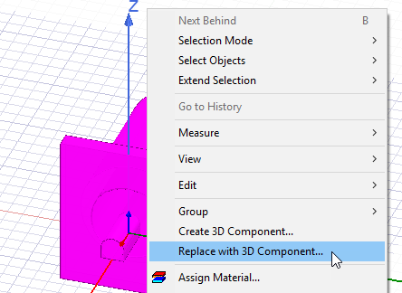
Replace Selection by 3D Component
To replace a selection in the 3D modeler window with a 3D component version of the selection, select an existing object or model, right-click, and select Replace with 3D Component. You can also click Draw> 3D Component Library> Replace with 3D Component. You cannot replace components from a design with an array setup. However, you create a 3D component from a unit cell and use that to create a Multi-Unit Cell array. When you replace a selection, object names are retained, port names are retained, component parameters map to existing design variables and report, field plot, and edit source are all preserved.
This command opens the Replace with 3D Component dialog box.
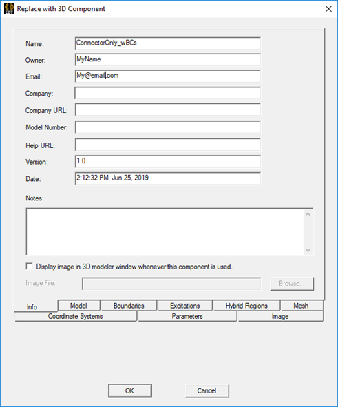
The tabs let you view the component features organized according to geometry, design data, and settings. The Replace with 3D Component dialog box does not offer tabs for encryption or licensing, compared to Creating a 3D Component. You can use these tabs to change inclusion of objects, boundaries, ports, coordinate systems, or parameters for the 3D component. When you click OK, no Save dialog box is shown.
- Info tab
- Model tab
- Boundaries tab
- Excitations tab
- Hybrid Regions tab
- Mesh tab
- Coordinate Systems tab
- Parameters tab
- Image tab
When you click OK, no save dialog is shown. The 3D component is saved to a temporary location. Insertion of instances uses the temporary file, but works just as regular 3D component insertion. The Project tree shows the Component under 3D Components, the boundaries are no longer listed under the Boundaries icon. Exictations, Reports and Analysis Setups remain the same. History Tree no longer shows detailed model edits. You can Undo and Redo.
Include or Exclude Feature from Component
You can view the various tabs and select which features to include or exclude while replacing the selection with a component. You can use the check boxes in the Include column for this purpose. You can also type a feature Namein the text box and use the Include or Exclude button. The text field supports wildcard characters (* and ?), so you can toggle the inclusion state for multiple objects with similar names in a single operation.
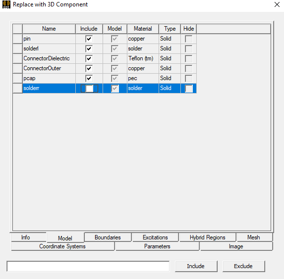
An object's Include option under the Model tab impacts the inclusion state in other tabs. For example, if you exclude an object from the component creation, the design data, parameters, and coordinate systems corresponding to that object are also excluded.
Sorting Columns Using the Headers
The features listed for each tab include columns for the Name, check boxes for whether to include, and properties. You can click on the column headers to sort by Name, Model, or other feature listed for each tab. Click the column header to selects the column to sort. Click again to invert the column.
You can sort lists by using all columns except Include.
Design Data Notes:
- DC thickness on selected objects is always included in components. It is not listed in the Boundaries tab.
- The Create 3D Component
dialog does not list design data without an assignment
- The parent of any included boundary/excitation is included, as long as the parent does not require assignment.
- Design settings like material overrides are included.
Once you have made the Include and Exclude settings, and have specified the Image and Info you click OK to Replace with 3D Component. When you click OK, the component is validated for everything that is included in the component. For example, you cannot include boundaries if the object on which the boundaries have been created is not included.