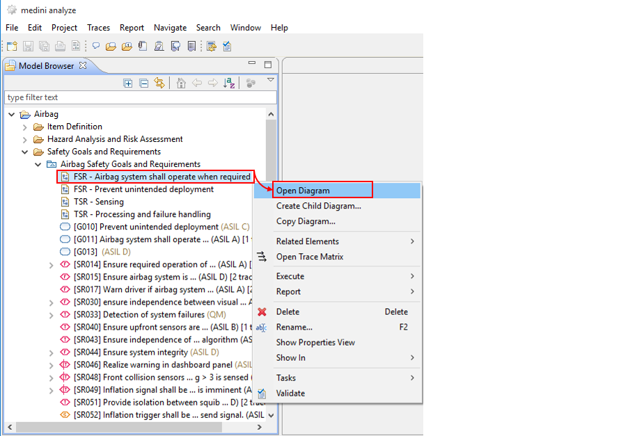
In order to edit safety requirements, safety goals, and their relations, the graphical goal modeling editor can be used. To open the editor, double-click on a safety requirement model icon, its diagram icon or any of the contained elements of the safety requirement model in the Model Browser. Choose the diagram, if multiple diagrams exist that contain the element.
There is one default diagram in each safety requirement model. Additional diagrams may be added using the context menu of either the model package ("New -> Diagram") or an existing diagram ("Copy Diagram" and "Create child diagram"). This is especially useful to keep large requirement models comprehensible for a human user (i.e. by breaking them down into multiple diagrams).
The requirement model editor consists of the diagram area, the palette and the tool bar as shown in the next figure. Note that this shows as example the ISO 26262 palette so your palette might look different. Please see Safety Domain Profiles for details.
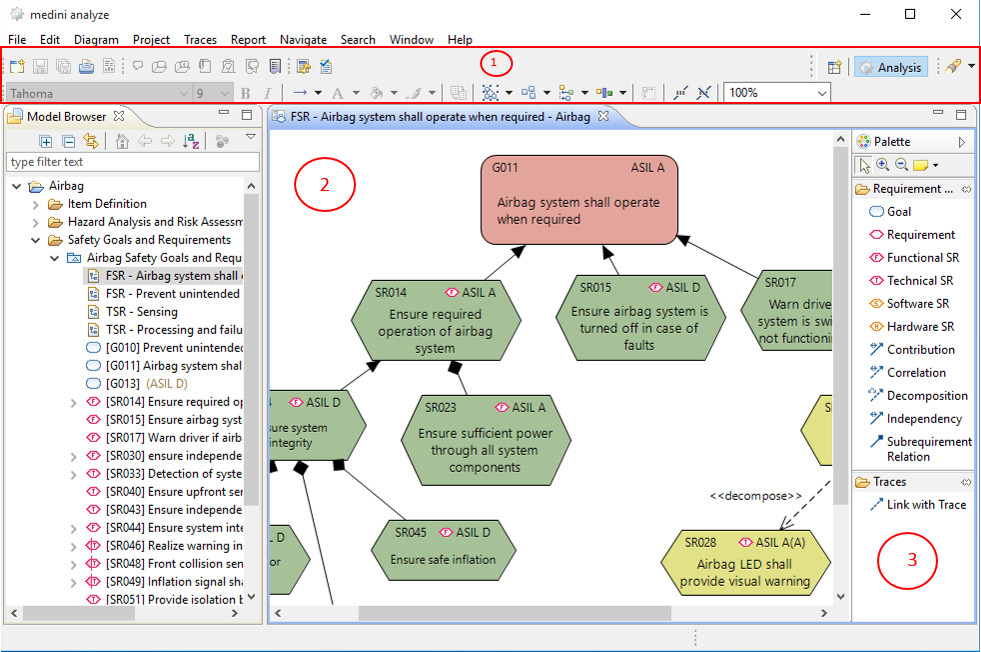
For general features of the graphical editor like formatting etc. please refer also to General aspects for graphical editors.
Elements can be created by dragging elements from the palette and dropping them on the diagram. If an element is created on the diagram, it also appears in the Model Browser.
The following model elements are available from the palette:
Goal: denotes a safety goal. This element is only available if supported by the corresponding domain (e.g. ISO 26262)
Requirement: denotes a safety requirement. This element is always available.
Functional, Technical, Software, Hardware SR : denotes a requirement of a special kind (this is a short cut to create these kinds of requirements directly, instead of creating a standard requirement and adjusting its kind via the property view.)
You can use drag & drop an existing element from the Model Browser onto any diagram in order to visualize it there. This works however only if the element is not yet shown on the diagram. Note that if safety goals have been created during the Hazard and Risk analysis (see Safety Goal Assignment), they are not shown automatically on a diagram, but can be added manually by drag and drop.
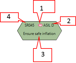
For each of the model elements a series of information is shown. Default values are assigned to following information parameters:
Requirement kind: indicated by the icon left of the safety integrity value (default value "unspecified")
Safety Integrity level: indicats the safety integrity level associated to the requirement in the top-right, i.e. the ASIL value for automotive (default value ASIL D), the DAL level for avionics, or the SIL level for IEC 61508.
Description: Textual description of the requirement. This is either the name field (default) or the description field of the safety requirement (if name is empty).
ID: unique identifier for safety requirements (as well as safety goals) created according to the applied auto-number schema
Some information can be modified directly on the diagram (integrity level, ID and name/description) by double-clicking on the text and modifying it. For more complex changes the property view or table/form editors must be used (see Table Editors for Safety Goals and Safety Requirements). These editors can be opened via the context menu of a safety goal or safety requirement on the diagram by the "Open With" entry.
The following kinds of connections are available to specify relationships:
Subrequirement relation: Safety requirements can be structured by containment, i.e. a requirement can be made up of several nested requirements or sub-requirements which refine it.
Contribution: this relation can be used between safety goals and/or safety requirements. It is drawn from the contributing element to the element to which it contributes. It denotes the requirements which are needed to fulfill a safety goal. Moreover, it can also be used to denote how the requirements contribute to each other in case they are not in the same sub-requirements hierarchy.
Correlation: this relation can be used between arbitrary safety goals, even if they are not in the same contribution hierarchy. It denotes that the achievement of one safety goal correlates with the achievement of another safety goal - even if there is not a direct contribution.
Decomposition (ISO 26262 only): for details see ASIL Decomposition (ISO 26262).
Independency (ISO 26262 only): for details see ASIL Decomposition (ISO 26262).
To draw a relation between elements, select the appropriate relation type from the palette and then draw the connection on the diagram. In order to redirect a relation from one element to another one, please click on the end of the relation arrow and just drag it to the new element.
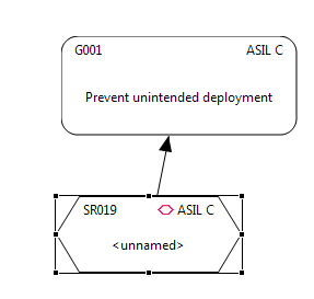
As a short-cut to create a Subrequirements-relation, drag and drop can be applied. This can be achieved by selecting the requirement symbol in the palette and clicking on an existing requirement in the diagram. A small + sign will appear while hovering with the mouse over the requirements symbol on the diagram to indicate the creation of a sub-requirement. The sub-requirement relation will be shown using a UML composition as depicted below. The newly created sub-requirement will automatically obtain the same safety integrity level as its parent requirement (here: ASIL). In the Model Browser, sub-requirements are shown as children of the respective parent requirement.
As a short-cut to connect a safety requirement with a safety goal by a Contribution-relation, drag and drop can be applied. This can be achieved by selecting the requirement symbol in the palette and clicking on an existing safety goal in the diagram. A small + sign will appear while hovering with the mouse over the safety goals symbol on the diagram to indicate the creation of a requirement. The newly created requirement will automatically obtain the same safety integrity level as the safety goal (here: ASIL). This can also be executed from the Model Browser.
If you drag sub-requirements from the Model Browser onto a diagram which already contains the parent requirement, appropriate sub-requirements relations will be shown automatically.
For all relations (except decomposition in ISO 26262) it is also possible to connect safety requirements between two different models. For example, an ISO 26262 project can setup two models, one for the functional safety concept and one for the technical safety concept as shown below:
The graphical editor supports visualization of any other safety goals and requirements model of the same project. Safety requirements can be drag and dropped into any diagram freely and connected afterwards. Safety requirements of a different model are decorated with a small "arrow" on the bottom right corner (see SR061 in the screenshot).
ASIL decomposition is offered by the ISO 26262 in order to reduce the ASIL of a certain safety requirement by splitting this requirement into two new requirements. However, these two requirements have to be sufficiently independent. ISO 26262 provides clear rules, which value the ASIL levels of these new safety requirements have to have.
In medini analyze, ASIL decomposition is supported by a special relation between safety requirements (available in the Automotive safety domain profile only). A decomposition can only be created using the safety requirements graphical editor.
The ASIL decomposition relation is created in the following way:
Create the safety requirement to be decomposed
Create two safety requirements into which it should be decomposed
Select the decomposition relation from the palette and draw it from the safety requirement which should be decomposed to the first safety requirement into which it should be decomposed
Create a second ASIL decomposition relation from the safety requirement which should be decomposed to the second safety requirement into which it should be decomposed
Adapt the ASIL value of the two target requirements to the desired value.
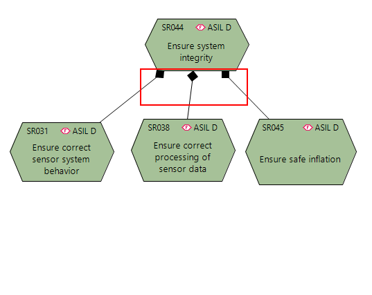
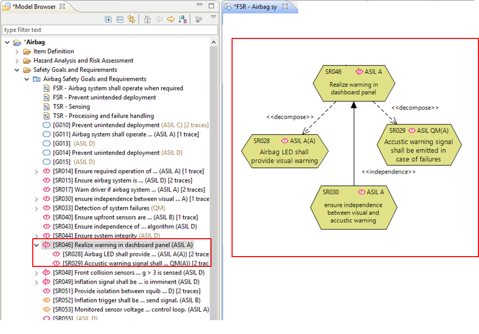
The result of the ASIL decomposition shown in the figure below.
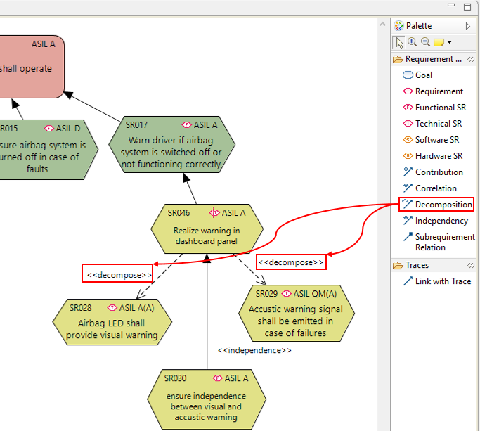
Note, it is not possible to decompose a safety requirement into more than two safety requirements by ASIL decomposition.
medini analyze checks the correct application of the ASIL decomposition rules of ISO 26262 when a validation is invoked (see Constraint validation and Default constraints). The following decomposition schemes are permitted by the standard:
ASIL D requirements
1 ASIL C and 1 ASIL A requirement
1 ASIL B and 1 ASIL B requirement
1 ASIL D and 1 ASIL QM requirement
ASIL C requirements
1 ASIL B and 1 ASIL A requirement
1 ASIL C and 1 ASIL QM requirement
ASIL B requirements
1 ASIL A and 1 ASIL A requirement
1 ASIL B and 1 QM requirement
ASIL A requirements
1 ASIL A and 1 ASIL QM requirement
Note, a scheme resulting in higher ASILs is also permitted.
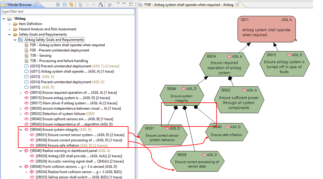
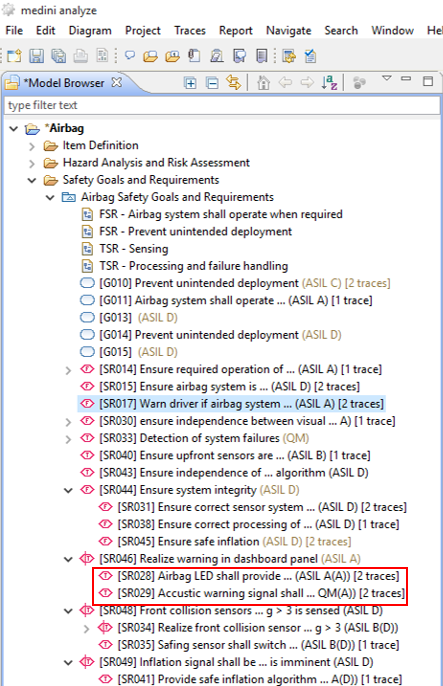
If a requirement is part of a decomposition, its entry in the Model Browser will show the ASIL of this requirement as well as the ASIL of its related safety goal. (e.g. ASIL A(B))
In the model browser, requirements participating in a decomposition are shown as children of the decomposed requirement which gets a special decorator.
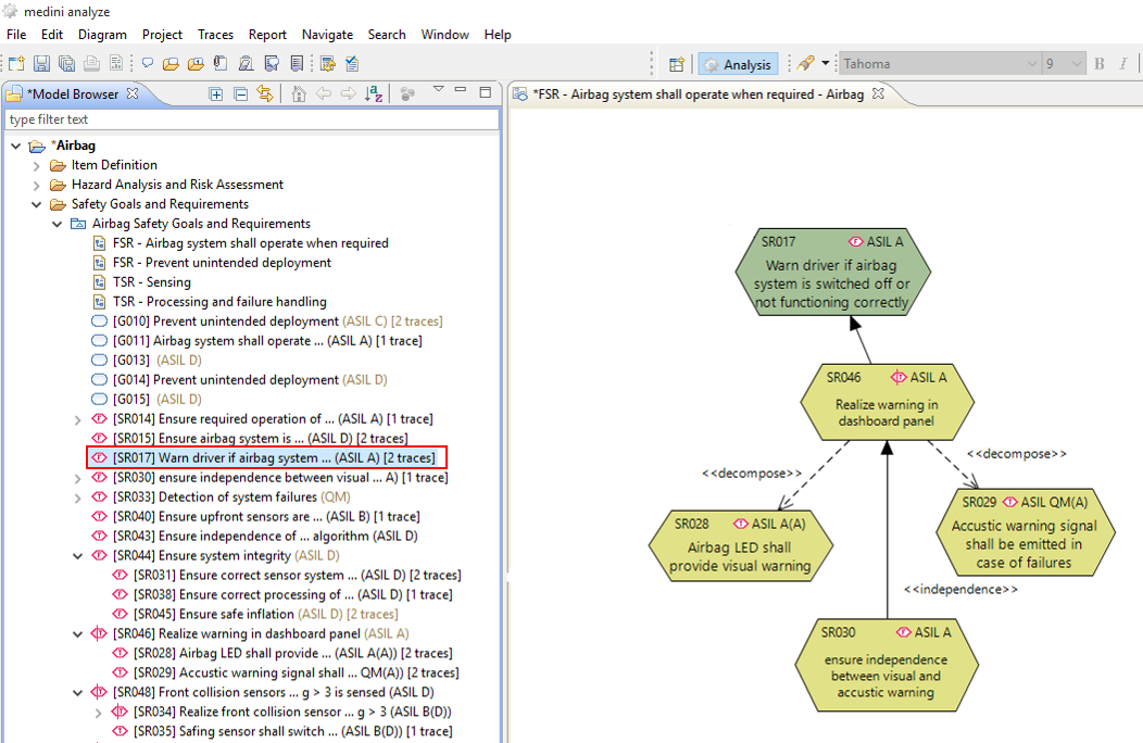
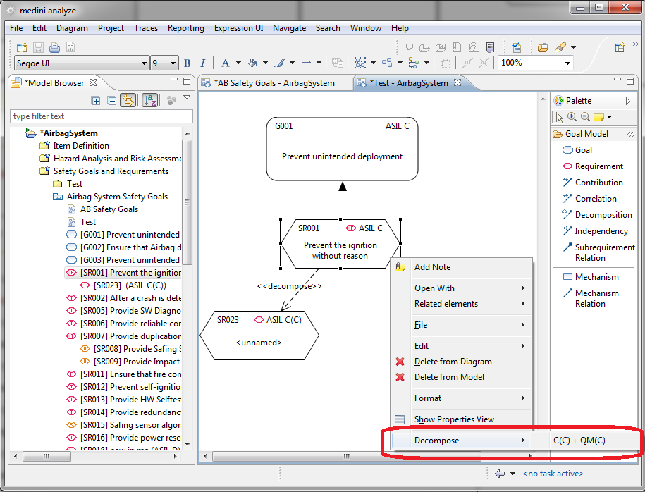
In order to ease the creation of the decomposition relation in the graphical editor, the context menu of a requirement on a diagram provides a new entry "Decompose". The sub-menu provides all valid combinations.
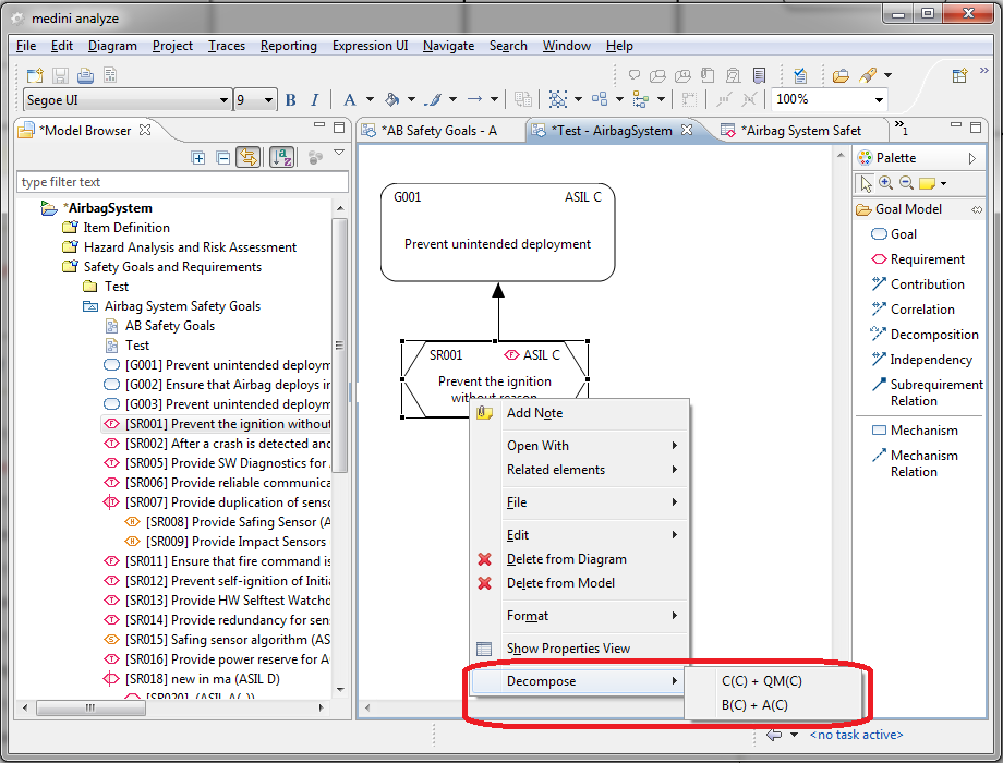
Note, that in case there is already one requirement that participates in the decomposition, only the remaining valid possibility wrt. ASIL is available via the context menu.
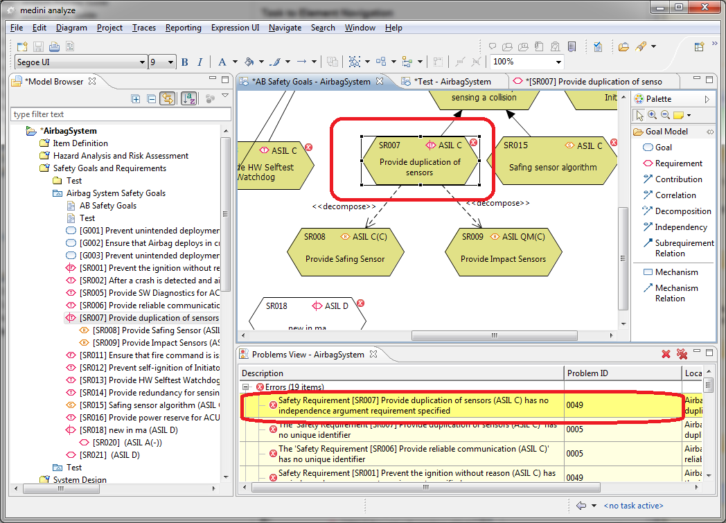
Please note, additional constraints apply to a decomposition. ISO26262 requires the provision of an independence argument. In medini analyze, the independence argumentation is provided as an additional requirement which is connected to a decomposed requirement via an "Independence" relation. This relation is created via the palette of the graphical editor like the other relations.
The presence of the "independency" relation as well as its ASIL (at least as high as the ASIL of the decomposed requirement) is checked for each decomposed requirement by the constraint validation of medini analyze (constraint 049, see Constraint validation).