


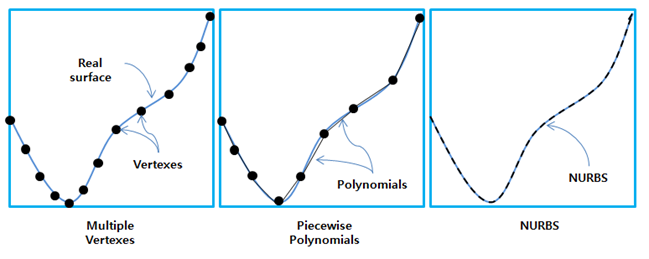
The contact geometry such as Faceset, Patchset, Edgeset, and Curveset can be represented using several methods such as multiple vertices, piecewise polynomials and splines as shown in the figure below. In the spline case, the Faceset can be represented by using a NURBS (Non-Uniform Rational B-Spline) from CAD and the Curveset can be represented by using Interpolation Functions from multiple passing points on a curve.
The representation methods can be different for each contact type as shown in the table below.
Figure 7.11: Available representation methods for contact geometry
| Type | Base Geometry | Action Geometry | ||||||
| Vertices | Polynomial | Spline | Vertices | Polynomial | Spline | |||
| General Contact |
Node Contact | Rigid body Base | X | O | O | O | X | X |
| FE body Base | X | O | X | O | X | X | ||
|
EasyFlex body Base | X | X | O | O | X | X | ||
|
Geometry Contact | Rigid to Rigid | X | O | O | O | O | O | |
| Flex to Rigid | X | O | O | O | O | X | ||
| Flex to Flex | X | O | X | O | O | X | ||
| Rigid to Rigid 3D Contact (RTR3D Contact) | X | O | O | O | O | O | ||
| Flex to Rigid 3D Contact (FTR3D Contact) | X | O | O | O | O | X | ||
| Flex to Flex 3D Contact (FTF3D Contact) | X | O | X | O | O | X | ||
| Tie Contact | X | O | X | O | X | X | ||
| Sphere to Multi-Curve Contact | X | X | O | X | X | Exact | ||
| Cylinder to Multi-Curve Contact | X | X | O | X | X | Exact | ||
| Multi-Curve to Multi-Curve Contact | X | X | O | X | X | O | ||
The accuracy, performance and stability for each representation method is summarized in the table below.
Figure 7.12: Representation method summary
| Type | Accuracy | Performance | Stability |
| Multiple Vertices | Low | Low | High |
| Piecewise Polynomials | Middle | Middle | Middle |
| Spline NURBS | High | High | Low |
| Spline AKIMA | High | High | High |
| Exact(Sphere, Cylinder) | High | High | High |
High accuracy in the table above means that the contact geometry is the closest to the real geometry. High performance means that it is the fastest method for finding contact points. High stability means that the method gives a consistent solution for various different shapes and conditions. For more information, see General Contact Properties.