From the property dialog of a Beam Group, the parameters of cross section, points, beam properties and body properties can be modified as shown in the figure below. Beam and body properties are automatically calculated from the shape of the cross section. The number of beam elements and bodies cannot be changed in the property dialog. If you want to change these numbers, you must create a new Beam group. Parameters for the cross section and properties of the beam and body are defined in the table below.
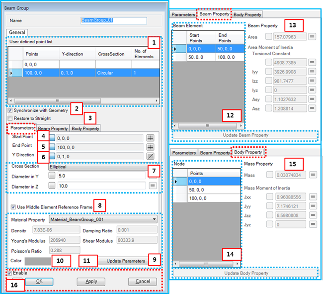
Figure 4.18: Description of parameters in the Beam Group property dialog
| Parameter | Symbol | Description | Dimension (Range) |
| 1. User defined point list | N/A | Displays the list of user-defined points for the beam group. Use this list to select a beam element in order to modify parameters or properties. To select a beam element, you must select the action point of that beam element. | N/A |
| 2. Synchronize with Geometry | N/A | When this option is selected, the properties of a beam element and body are automatically calculated from parameters such as cross section and material properties. When this option is cleared, you can input them directly. | N/A |
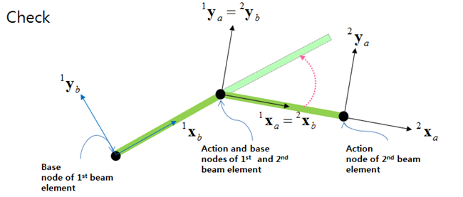
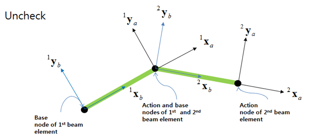
| 3. Restore to Straight | N/A | When this option is selected, the bent beam returns to straight under no load as shown in Figure 4.19: Restore to Straight option enabled. In this case, the orientation of the action marker for each beam element is equal to the orientation of the base marker of next beam element. When this option is cleared, the bent beam will remain bent under no load as shown in Figure 4.20: Restore to Straight option disabled. | N/A |
| 4. Start Point |

| Use to set the position of the base marker of the selected beam element by direct entry or by using the Point Picker. |
Length (Real) |
| 5. End Point |

| Use to set the position of action marker of the selected beam element by direct entry or by using the Point Picker. |
Length (Real) |
| 6. Y Direction |

| Use to set the reference direction using the Direction Picker. This is used to determine the z-axes of the base and action markers of the beam elements using Equation 4–138 in the Motion Theory Reference. |
N/A (Real) |
| 7. Cross Section | N/A | Use to set the type of cross section. Available types and their parameters are defined in Beam Group in the Motion Theory Reference. | N/A |
| 8. Use Middle Element Reference Frame | N/A | Use to set the element reference frame as Ae (Equation 4–140 in the Motion Theory Reference) in the middle of the beam element instead of Ab in Equation 4–153 ~ Equation 4–157 | N/A |
| 9. Material Properties | N/A | Use to select one of the pre-defined material properties settings. This panel shows the material properties such as density, damping ratio, Young's modulus, shear modulus and Poisson's ratio. Note that only linear elastic material is available for a Beam Group. For more information, refer to Material Properties. | N/A |
| 10. Color | N/A | Use to set the color of the beam group on the screen. | N/A |
| 11. Update Parameters | N/A | Apply the modified parameters to the selected beam elements by clicking this button. | N/A |
| 12. Beam Element | N/A | Displays the list of sub-beam elements of the selected beam element and can be used to select the sub-beam elements to change their properties. | N/A |
| 13. Beam Property | N/A | Displays beam properties such as cross-sectional area, area moment of inertia and shear area ratios as shown in Cross Sections and Equation 7–13 in the Motion Theory Reference. If the Synchronize with Geometry option is cleared, these properties can be set by direct entry. | Cross Sections in the Motion Theory Reference |
| 14. Node | N/A | Displays the list of body points of the selected beam element. Can be used to select the bodies to change their properties. | N/A |
| 15. Mass Property | N/A | Displays the body properties such as mass and mass moment of inertia as shown in Cross Sections and Equation 7–11 and Equation 7–12 in the Motion Theory Reference. If the Synchronize with Geometry option is cleared, these properties can be set by direct entry. | Cross Sections |
| 16. Control buttons | N/A | If all necessary parameters are set, these buttons are enabled. For more information about the control buttons, refer to Entity Properties Access and Modification. | N/A |