


The Point Picker is used to get a position of constraints, forces and various other entities that require a position by using geometry, design point, design frame, and so on. The Point Picker has various functions to get the position on the screen easily as shown in the figure and table below.
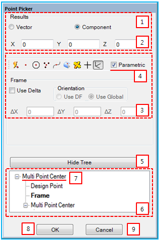
Figure 1.75: Description of Point Picker properties
| Property | Description |
|
1. Result |
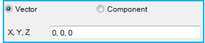
Select either Vector or Component to determine the format for displaying a position. When Vector is selected, the position will be displayed as follows.
|
| 2. Position | Show or enter a position of the resultant point. |
| 3. Filter | Set a Filter for the Point Picker. |
| 4. Parametric | Create a parametric relationship between the resultant point and the picking object. If the parametric option is selected, the resultant point will move when the picking object is moved. The parametric option is only available with some filters, such as MultiPointCenter, Rated, Design Point and Frame. |
| 5. Hide Tree | Hide the history tree. |
| 6. History Tree | Show the picker history, which contains the filters used and the picked objects and allows access to the filters in the history tree. This is useful when a picker has multi-step modeling depth and you change a point during the modeling steps. |
| 7. Operation | Access the filters and objects in multi-step modeling. |
| 8. OK/Parent | Return to the previous modeling step, applying the resultant point. When on the first modeling step, this closes the point picker. |
| 9. Cancel | Return to the previous modeling step without applying the resultant point. When on the first modeling step, this closes the point picker. |
The Point Picker has various filters which allow picking only a specific kind of object. The functionality of these filters is explained below.
Figure 1.76: Point Picker filters
| Filter | Symbol | Description |
| Any |
 | A point is determined automatically according to the selected object. It uses any of the filters below except the MultiPointCenter and Rated filters. |
| Cursor Location |
 | A point is determined by the cursor location. |
| Circle Center |
 | A point is determined from the center point of the selected circle, arc or sphere geometry. |
| MultiPointCenter |
 |
A point is determined from the center point of the selected points. The functionality is as follows.
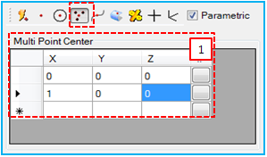
1. Enter positions in cells of the grid view or set the positions by the point picker. In each cell, the point picker button executes another point picker by switching the picker dialog. |
| Curve |
 |
A point is determined on the selected curve. The point on the curve can be controlled by a parameterized ratio (U). The functionality is as follows.
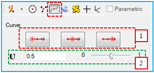
1. Set the U value with pre-defined values of 0, 0.5 and 1.0. 2. Set the U value between 0 to 1 by using the slider bar or entering the value directly. |
| Surface |
 |
A point is determined on the selected surface. The point on surface can be controlled by parameterized ratios (U and V). The functionality is as follows.
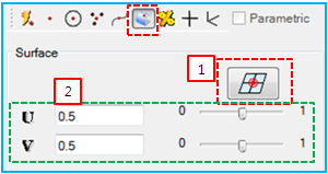
1. Set U and V with the pre-defined values of 0.5 and 0.5. 2. Set U and V values between 0 to 1 by using the slider bar or entering the values directly. |
| Rated |
 |
A point is determined between a pair of selected points. The point can be controlled by a ratio. The functionality is as follows.
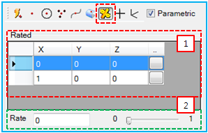
1. Define two points by entering the positions or using the point picker. 2. Set the rate value between 0 to 1 by using the slider bar. |
| Design Point |
 |
A point is determined by the selected Design Point. The functionality is as follows.
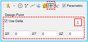
1. Use to input the delta of the point. When the parametric option is selected, Use Delta becomes available. The position can be determined as follows.
|
| Frame |
 |
A point is determined by the selected Marker or Design Frame. The functionality is as follows.
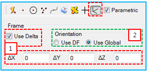
1. Use to set the delta. The definition is same as that for Design Point (above). 2. Use to set the reference frame for the delta. When Use DF is selected, the reference frame is set to the selected frame. When Use Global is selected, the reference frame is set to the inertia reference frame. |
