There are three ways to create a Beam Group as shown in the figures below. Passing points, direction, cross section, material and so on are defined in the Beam Group creation dialog. When creating the group, lumping bodies, matrix force and markers are simultaneously created to represent the group.
When the Point-Point option is used, the start and end points of the beam must be defined.
When the Multiple Points option is used, the number of points and each corresponding point must be defined.
When the File option is used, a text file which contains position vectors must be defined.
Parameters in the dialogs are as shown in the tables below.
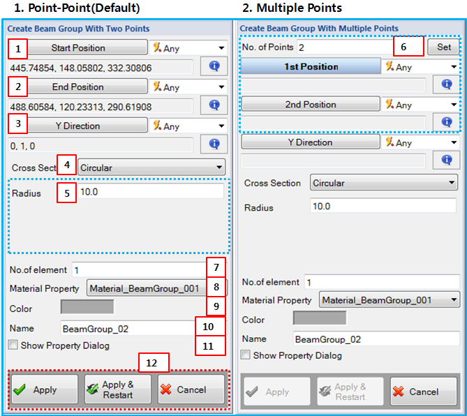
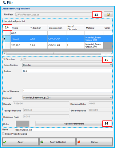
Figure 4.15: Description of parameters in the Beam Group creation dialogs
| Parameter | Description |
| 1. Start Position | Use to set the start point of the beam using the Point Picker. This becomes the position of the base marker of the first beam element. |
| 2. End Position | Use to set the end point of the beam using the Point Picker. This becomes the position of the action marker of the last beam element. |
| 3. Y Direction | Use to set the reference direction using the Direction Picker. This is used to determine the z-axes of base and action markers of the beam elements using Equation 4–138 in the Motion Theory Reference. |
| 4. Cross Section | Use to set the cross section of the beam element as shown in Cross Sections in the Motion Theory Reference. |
| 5. Geometry Property | Use to set the geometric parameters for the cross section as shown in Cross Sections in the Motion Theory Reference. |
|
6. No. of Point (for Multiple Points) | Use to set the number of passing points of the beam system. This value must be greater than 2. If the Set option is selected, the Position buttons to input additional points are displayed in the dialog. |
| 7. No. of Element | Use to set the number of beam elements between a point and the next point. |
| 8. Material Property | Use to set the material property of the beam elements. |
| 9. Color | Use to set the color of the beam elements. |
| 10. Name | Use to set the name of the Beam Group |
| 11. Show Property Dialog | Use to open the property dialog after finishing the creation operation. |
| 12. Control buttons | If all necessary parameters are set, these buttons are enabled. For more information about the control buttons, refer to Entity Creation. |
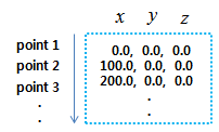
| 13. File Path | Use to select a file for the points. The file contains position vectors as shown Figure 4.16: File format for Beam Group (below). |
| 14. User defined point list | Display the points in the specified file and the parameters of the beam elements. A point and its adjacent point can be the start and end point of the beam element set. The row of the next point represents one beam element set. |
| 15. Parameters | Use to set the Y Direction and Cross Section parameters for the cross section along with No. of Element and Material. |
| 16. Update Parameters | Click this button to update parameters of the selected beam element sets. |